04 Ranger Ignition Switch Wiring Diagram – The first step is to look at the various types of terminals for the ignition switch. These terminals serve for the Ignition button, Coil and Accessory. After we’ve identified the terminals that are utilized and which ones are not, we can identify the different components of the 04 Ranger Ignition Switch Wiring Diagram. We’ll also discuss the functions and the Coil. We’ll then turn our attention to the accessory terminals.
The ignition switch’s terminals
Three switches are found in an ignition switch. Each of the three switches feeds the battery’s voltage to various places. The first one supplies power to the choke when it is pushed. The third is the switch that controls the ignition’s ON/OFF positions. Different manufacturers have different colors-coding systems to match the conductors. OMC utilizes this system. The connector permits the connection of a speedometer to the ignition switch.
While most ignition switch terminals aren’t authentic, the numbering of each might not be consistent with the diagram. Before plugging into the ignition switch make sure to check the continuity. This can be done with an inexpensive multimeter. Once you are happy with the continuity of the wires it is time to install the new connector. The wiring loom of an ignition switch that’s factory-supplied will be different than the one you have in your car.
Before you can connect the ACC outputs to your car’s auxiliary outputs, it is important to know the fundamentals of these connections. The ACC/IGN terminals function as the default connections on the ignition switch. The START/IGN terminals are connected to the radio or stereo. The ignition switch switches the engine of your car ON and off. Older cars are equipped with ignition switch terminals labeled “ACC” or “ST” (for individual magnetowires).
Terminals for coil
Understanding the terminology is the first step towards finding out what kind of ignition coil you’ve got. The fundamental diagram of ignition wiring shows a number different connections and terminals. There are two primary and secondary connections. Each coil operates at a specific voltage. The first step to determine which kind you’re using is to examine the voltage of S1 or the primary terminal. To determine if the coil is a Type A, C, or B coil, you must also test the resistance on S1’s.
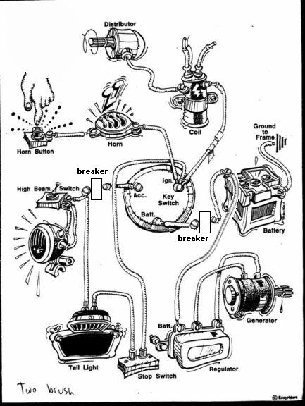
The coil’s low-tension side must be connected to the chassis positive. This is also the ground on the ignition wiring diagram. The high-tension component connects the spark plugs to a positive. To reduce the noise, the coil’s metal body must be connected to the chassis. However, it is not required to connect electrically. It is also possible to see the connections between the positive and the negative coil’s terminals on an ignition wiring diagram. Sometimes, a defective ignition coil can be identified by a scan done in an auto parts shop.
The black-and-white-striped wire from the harness goes to the negative terminal. The white wire is black and goes to the terminal opposite. The contact breaker is connected to the black wire. To check the connections between the two wires employ a paperclip to remove them from the housing. Also, make sure to ensure that the terminals have not been bent.
Accessory terminals
Diagrams of ignition wiring show the wiring used in the vehicle’s power supply. There are generally four color-coded terminals to each component. The red symbol represents accessories, yellow is for the battery and green for the starter solenoid. The “IGN terminal” is used to power the wipers and other operating functions. The diagram illustrates how you can connect ACC or ST terminals and the rest.
The terminal known as BAT is where the battery is connected. The electrical system will not start if the battery isn’t connected. The switch won’t turn on if the battery isn’t present. You can view your wiring diagram to determine where your car’s batteries are placed. The ignition switch is connected to the battery of your car. The BAT terminal is connected to the battery.
Certain ignition switches have an additional position in which users can modify their outputs as well as control them without the need to use the ignition. Some customers prefer to use an auxiliary output that is independent of the ignition. You can utilize the additional input by connecting it to the ACC terminal. This feature is convenient, but it has one major distinction. The majority of ignition switches are set to have an ACC position when the car is in the ACC position, whereas they’re set to the START position when the car is in the IGN position.
Gallery of 04 Ranger Ignition Switch Wiring Diagram
Gallery of 04 Ranger Ignition Switch Wiring Diagram


