04 Triumph Ignition Wiring Diagram – We’ll begin by looking at the various types terminals found in an ignition switch. These terminals are used for the Ignition button, Coil and Accessory. Once we’ve established the purpose of these terminals, we will be able to determine the various components of the ignition wiring. Then, we will discuss the functions for the Ignition switch, as well as the Coil. Following that, we’ll shift our attention to the Accessory terminals.
Terminals for ignition switches
There are three different switches on an ignition switch that provide the battery’s voltage to various destinations. The first one supplies power to the choke when pushed, and the second is the ignition switch’s ON/OFF position. Different manufacturers have various color codes for the different conductors. This is explained in a separate article. OMC uses this method. Connectors can be connected to the ignition switch in order to include an electronic tachometer.
Although most ignition switch terminals are duplicated, the numbers might not match the diagram. Check the electrical continuity to determine if they’re connected to the correct ignition switch. A cheap multimeter can assist you in this. When you’re satisfied that the wires are in good continuity and you are able to connect the new connector. The wiring loom for an ignition switch that’s factory-supplied will be different than the one in your car.
Knowing how the ACC outputs connect to the auxiliary outputs of your vehicle is crucial. The ACC and IGN terminals are the default connections for your ignition switch, and the START and IGN terminals are the primary connections for the stereo and radio. The ignition switch’s function is to turn the engine of your car on and off. On older cars the terminals of the ignition switch are identified with the letters “ACC”, and “ST” (for individual magnetic wires).
Terminals for coil
To determine the type of ignition coil, the initial step is to understand the terminology. In a basic ignition wiring diagram you’ll see several different connections and terminals, which include two primary and two secondary. You need to determine the kind of coil you have by testing the voltage on the primary terminal, called S1. S1 should also be checked for resistance in order to identify if it’s a Type B, B or A coil.
The coil’s low-tension side should be connected to the chassis’ minus. This is the base of the ignition wiring. The high-tension part connects the spark plugs to a positive. The aluminum body of the coil needs to be linked to the chassis for suppression however it’s not electrically required. The wiring diagram will illustrate the connection between the positive and negative coil terminals. Sometimes, an inspection at an auto parts shop can diagnose a malfunctioning ignition wire.
The black-and-white-striped wire from the harness goes to the negative terminal. The positive terminal receives the other white wire with the trace of black. The black wire is connected to the contactbreaker. It is possible to check the connections with a paperclip to pull the wires out of the housing. It is also important to see that the terminals aren’t bent.
Accessory terminals
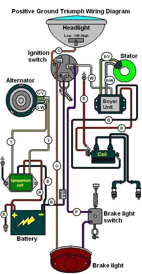
Diagrams of ignition wiring show the wires used to power various parts of the car. Each component is equipped with four distinct color-coded connections. Accessories are red, the battery is yellow and the starter solenoid is green. The “IGN terminal is used to start the car, operating the wipers, and for other functions. The diagram below illustrates how to connect the ACC terminal and ST terminals to the other components.
The terminal BAT is the connection for the battery. The electrical system won’t start without the battery. A dead battery could cause the switch to not come on. You may refer to the wiring diagram if you’re not sure where the batteries of your car are. Your car’s accessory terminals are connected to the ignition switch and the battery. The BAT connector connects to your battery.
Some ignition switches come with an additional “accessory position” that allows users to adjust their outputs independently of the ignition. Some customers may prefer to use the auxiliary output independently of the ignition. To make use of the auxiliary output, connect the connector using the same colors as the ignition, connecting it to the ACC terminal on the switch. Although this is a great feature, there’s one thing to be aware of. Most ignition switches are configured to operate in the ACC position when the vehicle is in the ACC position, whereas they’re in the START position when the vehicle is in the IGN position.
Gallery of 04 Triumph Ignition Wiring Diagram
Gallery of 04 Triumph Ignition Wiring Diagram


