1955 6 Volt Ford Ignition Wiring Diagram – The first step is to look at the different terminals that are used in the ignition switch. These terminals are for the Ignition button, Coil and Accessory. Once we have identified the purpose of these terminals and what they do, we can then determine the various components in the ignition wiring. We’ll also be discussing the functions of the Ignition switch and Coil. Then, we’ll talk about the roles of the ignition switch and Coil.
Terminals for ignition switches
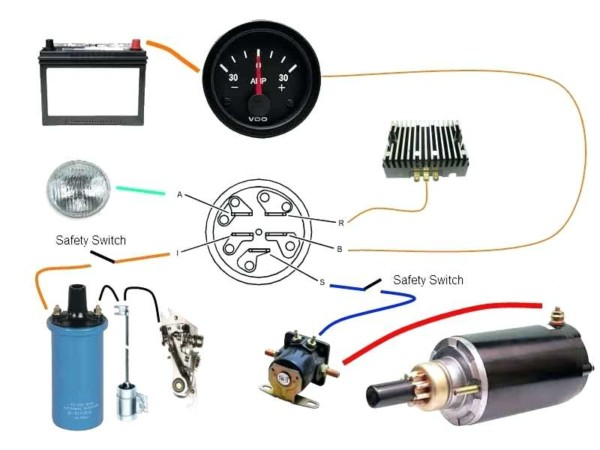
An ignition switch has three different switches that direct the battery’s current to different locations. The first switch provides the choke with power, while the second switch controls the state of the switch. Different manufacturers have distinct color-coding systems that correspond to the conductors. OMC utilizes this method. The ignition switch comes with a connector for adding the tachometer.
Although the majority of ignition switch terminals don’t come in original form, the numbering may not be in line with the diagram. The first step is to check the continuity of all wires to ensure that they are properly connected to the ignition switches. You can do this with a simple multimeter. After you’ve confirmed the integrity of the wires you are able to connect the connector. The wiring loom used for the ignition switch supplied by the factory will be different from the one in your vehicle.
For connecting the ACC outputs to the auxiliary outputs on your vehicle, you have to first understand the way these two connections function. The ACC and IGN connectors are the default connections of your ignition switch. While the START, IGN, and ACC terminals are the main connections for the radio or stereo, the START/IGN connections are the main ones. The ignition switch is the one that turns the car’s engine to and off. The terminals on older cars’ ignition switches are labeled by “ACC” and ST (for the individual magneto wires).
Coil terminals
To determine the type of ignition coil, the initial step is to understand the terminology. An ignition wiring diagram will show a variety of connections and terminals, which include two primary terminals and two secondaries. Each coil is equipped with a distinct operating voltage. To determine which type of coil you’ve got the first step is to test the voltage at the S1 primary terminal. S1 should also be checked for resistance to determine if the coil is a Type B, B, or an A coil.
The negative of the chassis must be connected to the low-tension side. This is the wiring diagram you will see on the wiring diagram. The high-tension end is a positive connection to the sparkplugs. To prevent noise the coil’s body metal is required to be connected to the chassis. This is not necessary for electrical use. The diagram of the ignition wiring will also show how to connect the positive coil terminals. Sometimes, a defective ignition coil can be identified by a scan done at an auto parts shop.
The black-and-white-striped wire from the harness goes to the negative terminal. The other white wire is black and goes to the negative terminal. The black wire is connected to the contact breaker. To verify the wires’ connections, use a paperclip and lift them out of the housing. Make sure that the terminals don’t bend.
Accessory terminals
Diagrams of ignition wiring illustrate the wires used in the vehicle’s power supply. Each component has four distinct connections that are color coded. The accessories are colored red, the battery is yellow, the starter solenoid green. The “IGN terminal” is used to power the wipers along with other operational features. The diagram illustrates how to connect ACC or ST terminals and the rest.
The terminal BAT holds the battery. The electrical system is not able to begin without the battery. Additionally, the switch will not be able to turn on without the battery. To find the battery in your car examine the wiring diagram. The ignition switch and battery are connected by the accessory terminals. The BAT connector connects to your battery.
Certain ignition switches come with an additional position in which users can modify their outputs as well as control them without needing to use the ignition. Sometimes, customers wish to utilize an auxiliary output that is separate from the ignition. For the auxiliary output to be used, connect the connector to the same shade as that of the ignition. Then connect it with the ACC end of the switch. This convenience feature is great however there’s a distinction. The majority of ignition switches are designed to show an ACC status when the car’s at either the ACC or START position.
Gallery of 1955 6 Volt Ford Ignition Wiring Diagram
Gallery of 1955 6 Volt Ford Ignition Wiring Diagram


