1956 Chevy Ignition Switch Wiring Diagram – Let’s first examine the various terminals used on the ignition switch. These are the terminals that connect the Ignition, Coil, or Accessory. After we’ve identified the purpose of these terminals, it is possible to identify the various parts of the ignition wiring. Then, we will discuss the roles of the Ignition switch and the Coil. Following that, we will discuss the Accessory Terminals.
Terminals for ignition switches
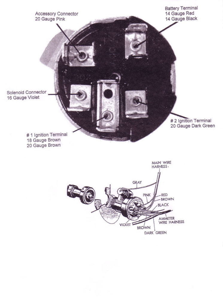
The ignition switch is comprised of three different switches that direct the battery’s current to different locations. The first switch is used to turn on the choke through pushing it, while the third switch is used to control the ON/OFF position. Different manufacturers have distinct colour-coding systems that correspond to the conductors. OMC utilizes this procedure. The connector allows for the connection of a speedometer to the ignition switch.
While many ignition switch terminals do not come in original form The numbering might not match that of the diagram. Check the continuity of all wires to ensure they are correctly connected to the ignition switches. A simple multimeter will help you do this. Once you are satisfied with the continuity of the wires you can connect the new connector. If you’re using an ignition switch that is supplied by the manufacturer the wiring loom may be different from the one used in your vehicle.
Understanding how ACC outputs are connected to the auxiliary outputs in your car is vital. The ACC and IGN connectors are the standard connections for your ignition switch. The START, IGN, and ACC terminals are the main connections for the radio or stereo, the START/IGN connections are the most important ones. The ignition switch is the one that controls the engine of your car. Older cars are equipped with ignition switch terminals labeled “ACC” or “ST” (for individual magnetowires).
Terminals for coil
To figure out the type of ignition coil you need to know the step is to learn the definition of. A basic ignition wiring diagram will show a variety of connections and terminals, comprising two primary and two secondaries. Each coil is operating at a certain voltage. The first step in determining which type you have is to check the voltage on S1, or the primary terminal. S1 must be tested for resistance in order to determine if the coil belongs to type A, B and/or C.
The coil’s low-tension side is to be connected to the chassis’ positive. This is what is known as the ground for the ignition wiring. The high-tension end supplies positive direct to the sparkplugs. It is necessary for the purpose of suppression that the body of the coil’s metal be connected to the chassis, but not essential. There are also connections between the positive and the negative coil’s terminals on an ignition wiring diagram. Sometimes, a malfunctioning ignition coil can be identified through a scan performed at an auto repair shop.
The black-and-white-striped wire from the harness goes to the negative terminal. The white wire also has a black trace on it and it goes to the positive terminal. The black wire is connected to the contact breaker. To verify the connections between the two wires, employ a paperclip to lift them from the housing. Make sure you don’t bend the connectors.
Accessory terminals
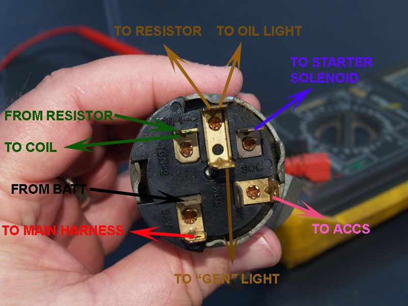
Diagrams of ignition wiring illustrate the wiring used to power various parts of the vehicle. Each component has four distinct connections that are color coded. The red color is for accessories, yellow the battery, and green is the starter solenoid. The “IGN” terminal allows you to start the car, manage the wipers, or any other operation features. This diagram demonstrates how to connect ACC and ST terminals with the other components.
The battery is attached to the terminal named BAT. Without the battery, the electrical system does not start. Also, the switch won’t be able to turn on without the battery. To locate your car’s battery, check your wiring diagram. The accessory terminals of your car are connected with the battery as well as the ignition button. The BAT Terminal is connected to the Battery.
Certain ignition switches come with the “accessory” position that allows users to regulate their outputs without having to use the ignition. Some customers might want to use the auxiliary output separately from the ignition. You can use the additional output by connecting it to the ACC terminal on your switch with the same colors. While this is an excellent feature, there’s one significant difference. A majority of ignition switches feature the ACC position when your vehicle is in the ACC mode and a START position when the switch is in IGN.
Gallery of 1956 Chevy Ignition Switch Wiring Diagram
Gallery of 1956 Chevy Ignition Switch Wiring Diagram


