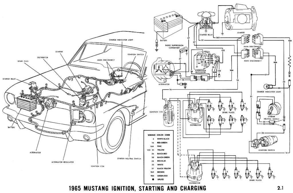
1965 Mustang Ignition Switch Wiring Diagram – In the beginning, we’ll take a look at the various kinds of terminals that are found in the ignition switch. These are terminals for the Ignition, Coil, or Accessory. Once we have identified the purpose of these terminals and what they do, we can then determine the various components in the ignition wiring. We’ll also discuss the functions and the Coil. We’ll then turn our attention on the accessory terminals.
The terminals of the ignition switch
An ignition switch is comprised of three switches. They supply the voltage of the battery to different places. The first switch powers the choke. The second switch controls the ON/OFF of the ignition switch. Different manufacturers employ different color codes for various conductors. This is explained in a different article. OMC follows this scheme. The connector permits the attachment of a speedometer the ignition switch.
Although some ignition switch terminals may not be original, the numbering of each one might not be in line with the diagram. To make sure that your wires are correctly connected to the switch, it is recommended to check their continuity. A multimeter is a great tool to check the continuity. When you are happy with the continuity of the wires, you can connect the new connector. The wiring loom in the ignition system switch supplied by the manufacturer is distinct.
For connecting the ACC outputs to the auxiliary outputs of your car, you’ll need to understand how these two connections work. The ACC and IGN connectors are the standard connections of your ignition switch. Although the START, IGN, and ACC terminals are the main connections for the radio or stereo, the START/IGN terminals are the main ones. The ignition switch controls the car’s engine. Older vehicles have ignition switch terminals marked “ACC” or “ST” (for individual magnetowires).
Terminals for coil
Understanding the terminology is the initial step to finding out what kind of ignition coil you have. The basic ignition wiring diagram shows a number different connections and terminals. There are two primary and one secondary. You need to determine the kind of coil you have by testing the voltage at the primary terminal, called S1. It is also recommended to check S1 for resistance in order to determine whether it is an A, B, or C coil.
The coil’s low-tension side should be connected to the chassis’ minus. This is also the ground on the wiring diagram for ignition. The high-tension side supplies positive direct to the sparkplugs. The coil’s aluminum body needs to be linked to the chassis for suppression, but it isn’t electrically required. The ignition wiring diagram will also show the connections of the positive coil terminals. It is possible to find an issue with the ignition coil that can be easily diagnosed by looking it up at an auto parts retailer.
The black-and-white-striped wire from the harness goes to the negative terminal. The negative terminal is served by the black trace that’s attached to the white wire. The black wire is connected to the contact breaker. If you’re not sure about the connection between both, you can use a paper clip to remove them from the housing of the plug. Also, make sure to verify that the connections haven’t been bent.
Accessory terminals
Diagrams of ignition wiring depict the wires used to provide power to various components of the vehicle. There are typically four different colors-coded terminus of each part. For accessories, red is the starter solenoid’s color, yellow is for battery and blue for accessories. The “IGN terminal” is used to run the wipers, as well as other operating features. The diagram demonstrates how to connect the ACC and ST terminals to the rest of the components.
The terminal known as BAT is the location where the battery is. The electrical system can’t start without the battery. In addition, the switch doesn’t turn on. A wiring diagram can inform you the location of the battery of your car. The accessory terminals of your car connect to the ignition switch as well as the battery. The BAT connector is connected to the battery.
Some ignition switches feature an additional “accessory” position, where users can manage their outputs with no ignition. Sometimes, a customer wants to use the auxiliary output separate from the ignition. You can use the additional output by connecting the connector to an ACC terminal on the switch using the same colors. This feature is convenient, but it has one significant distinction. Most ignition switches will have an ACC position when the vehicle is in ACC however, they will be at the START position when the vehicle is IGN.
Gallery of 1965 Mustang Ignition Switch Wiring Diagram
Gallery of 1965 Mustang Ignition Switch Wiring Diagram


