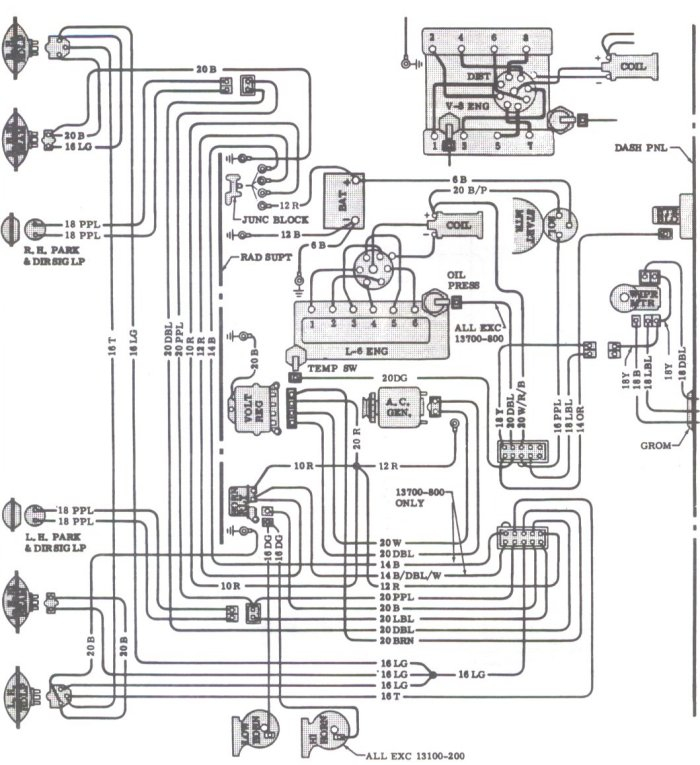
1966 Chevelle Ignition Switch Wiring Diagram – First, we will look at the various types of terminals on the ignition switch. These are the terminals that connect the Ignition, Coil, or Accessory. After we’ve identified the terminals that are utilized and which ones are not, we can determine the various components of the 1966 Chevelle Ignition Switch Wiring Diagram. We’ll also discuss the roles of the Ignition switch and Coil. We’ll then turn our attention on the accessory terminals.
Terminals for ignition switch
Three switches can be found in an ignition switch. Each of these three switches transmits the battery’s current to various places. The first switch powers the choke. The third switch regulates the ON/OFF function of the ignition switch. Different manufacturers employ different color codes for various conductors. This is explained in a different article. OMC utilizes this method. Connectors can be attached to the ignition switch in order to include an electronic Tachometer.
Even though some ignition switch terminals don’t have the original design however, the numbers may not match the diagram. Check the continuity of all the wires to make sure they’re properly plugged into the ignition switches. A multimeter that is inexpensive can assist you in this. Once you’ve verified the continuity of the wires you are able to connect the connector. The wiring loom of a factory-supplied ignition system switch is distinct.
Understanding how the ACC outputs are connected to the auxiliary outputs in your car is vital. The ACC, IGN and START terminals are the default connection to the ignition switch. They are also the primary connections to your radio and stereo. The ignition switch controls the car’s engine. The terminals for the ignition switch on older cars are labeled with the letters “ACC” as well as “ST” (for each magneto wires).
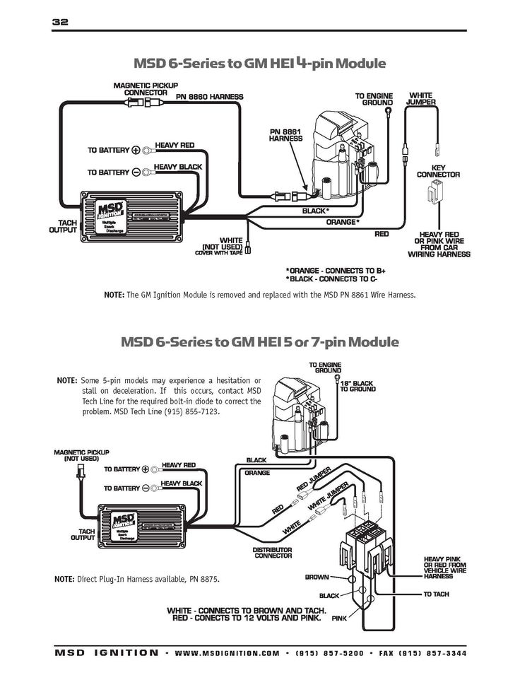
Terminals for coil
The first step to determine the kind of ignition coil is to understand the terminology that is used. The basic ignition wiring diagram shows a number different connections and terminals. There are two primary and secondary connections. The operating voltage of every coil is different. Therefore, it is important to first test the voltage at S1 (primary terminal). To determine whether it’s a Type A, C, or B coil it is recommended to also test S1’s resistance.
The chassis’ negative needs to be connected to the side of low-tension. This is also the ground on the ignition wiring diagram. The high-tension side connects the spark plugs to a positive. The aluminum body of the coil needs to be linked to the chassis to prevent it from being smothered however it’s not electrically required. You will also see the connections of the positive and the negative coil terminals on the ignition wiring diagram. Sometimes, a damaged ignition coil can be detected through a scan performed in an auto parts shop.
The black-and-white-striped wire from the harness goes to the negative terminal. The other white wire is black with a trace on it, and it goes to the positive terminal. The black wire connects to the contact breaker. To check the wires’ connections, employ a paperclip to lift them off the housing. Be sure that you don’t bend the connectors.
Accessory terminals
The diagrams for ignition wiring show the wiring used to power the vehicle’s electrical supply. There are typically four colored terminals that correspond to each component. The red color represents accessories, yellow represents the battery and green for the starter solenoid. The “IGN terminal allows you to start the car, control the wipers or other features that operate. The diagram demonstrates how to connect the ACC and ST terminals to the rest of the components.
The terminal BAT is where the battery is. The battery is vital to allow the electrical system to start. The switch won’t turn on if there is no battery there. The wiring diagram will tell you the location of the battery in your car. The ignition switch as well as the battery are connected via accessory terminals. The BAT terminal is connected to the battery.
Some ignition switches feature an “accessory” setting that permits users to control their outputs without needing to turn on the ignition. Sometimes, customers want to utilize an auxiliary output that is separate from the ignition. You can utilize the additional input by connecting the connector to the ACC terminal. Although this is a fantastic feature, there’s something you should know. A majority of ignition switches feature the ACC position when your vehicle is in ACC mode and a START mode when you are in IGN.
Gallery of 1966 Chevelle Ignition Switch Wiring Diagram
Gallery of 1966 Chevelle Ignition Switch Wiring Diagram


