1966 Mustang Ignition Switch Wiring Diagram – Let’s begin by looking at the different types terminals found in an ignition switch. These are the terminals for the Ignition, Coil, or Accessory. Once we’ve established the purpose of these terminals, we will be able to determine the various components of the ignition wiring. We will also discuss the functions for the Ignition switch and the Coil. We will then concentrate on the accessory terminals.
Terminals for ignition switches
An ignition switch has three switches. They feed the battery’s voltage to different places. The first switch provides the choke with power, while the second toggles the on/off state of the switch. Every manufacturer has its unique color-coding system, which we will discuss in another article. OMC follows this system. Connectors can be attached to the ignition switch to add an electronic tachometer.
Although the majority of ignition switch terminals do not have the original design The numbering might not match that of the diagram. Before plugging into the ignition switch, make sure to check the continuity. A multimeter is an excellent instrument to verify the continuity. Once you are satisfied that all wires are in good order and you are able to connect the new connector. If your vehicle is equipped with an ignition switch installed the wiring diagram will differ.
You must first understand the way that ACC outputs and the auxiliary outputs function to connect them. The ACC and IGN terminals are the default connections on the ignition switch. the START and IGN terminals are the principal connections for stereo and radio. The ignition switch acts as the engine’s on/off button. The terminals of older vehicles’ ignition switches are labeled by “ACC” and ST (for individual magneto wires).
Terminals for coil
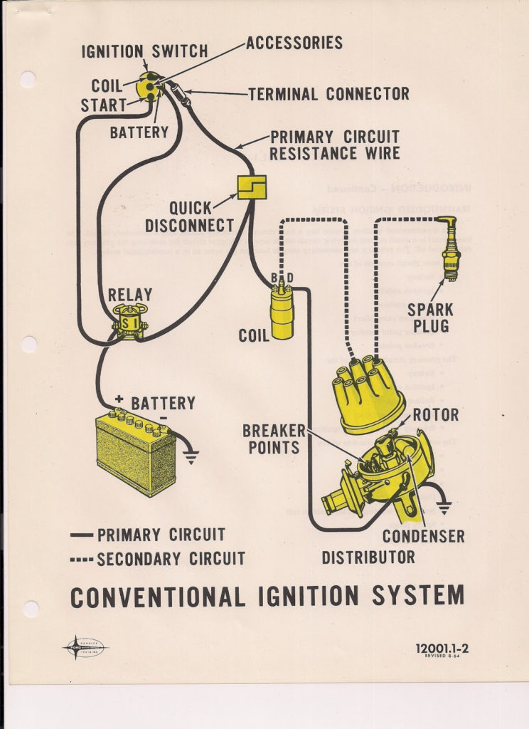
To figure out the type of ignition coil, the initial step is to know the definition of. The basic ignition wiring diagram depicts various connections and terminals. There are two primary and one secondary. Each coil is equipped with a distinct operating voltage. To determine the type of coil you own, the first step is to test the voltage at the S1 primary terminal. S1 should be checked for resistance to determine if the coil belongs to Type A, B, or C.
The low-tension end of the coil must be connected to the chassis’ negative. This is the ground in the diagram of the ignition wiring. The high-tension side connects the spark plugs to a positive. The metal body of the coil needs to be connected to the chassis for suppression purposes however it isn’t electrically required. The wiring diagram for the ignition will demonstrate how to connect the terminals of either the positive and negative coils. There could be an issue with your ignition coil which can be identified by scanning it in an auto parts store.
The black-and-white-striped wire from the harness goes to the negative terminal. The terminal for the negative is served by the trace in black that’s attached to the white wire. The black wire connects to the contact breaker. To test the wires’ connections use a paperclip and remove them off the housing. It is also important to ensure that the terminals don’t bend.
Accessory terminals
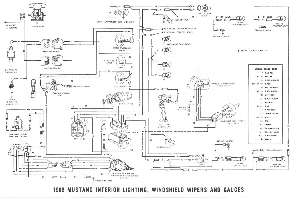
Diagrams of ignition wiring depict the wires that provide power to various components of the vehicle. There are generally four colored terminus lines for each component. The red color is for accessories, yellow to the battery and green the starter solenoid. The “IGN terminal is used to start the car, operating the wipers and other functions. The following diagram shows how to connect the ACC terminal as well as the ST terminals to various components.
The battery is attached to the terminal named BAT. The battery is necessary for the electrical system to get started. The switch will not turn on if the battery isn’t present. If you don’t know the location of your car’s battery located, you can review the wiring diagram of your car to determine how to locate it. The ignition switch and battery are connected via accessory terminals. The BAT terminal is connected to the battery.
Some ignition switches offer the option of an “accessory position” that allows users to modify their outputs independent of the ignition. Customers may want to use the auxiliary output in addition to the ignition. The auxiliary output can be used to connect the connector with the same colors as your ignition, and then connecting it to the ACC terminal of the switch. This feature of convenience is fantastic however there’s a distinction. Most ignition switches will be in an ACC position if the car is in ACC, but they’ll be in the START position if the vehicle is in IGN.
Gallery of 1966 Mustang Ignition Switch Wiring Diagram
Gallery of 1966 Mustang Ignition Switch Wiring Diagram


