1968 Camaro Ignition Coil Wiring Diagram – We will first look at the various types of terminals for the ignition switch. They include terminals for the Ignition switch, Coil, and Accessory. Once we understand the function of each type of terminal, it is possible to identify the parts of the ignition wiring. We will also talk about the functions and the Coil. We will then discuss the function of the ignition switch and Coil.
Terminals for ignition switches
There are three different switches on an ignition switch, which provide the battery’s voltage to various places. The first one is used to drive the choke through pushing it, while the third switch is used to control the ON/OFF setting. Each manufacturer has their unique color-coding system, which we will discuss in another article. OMC follows this scheme. There is a connector inside the ignition switch for attaching a to a tachometer.
Although the majority of ignition switch terminals don’t have an original number, they may be equipped with a different number. Before plugging in the ignition switch, make sure to check the continuity. This can be checked with a multimeter that is inexpensive. After you’ve confirmed that the wires are in good condition, you are able to install the connector. The wiring loom of a factory-supplied ignition system switch differs.
Before connecting the ACC outputs to your car’s auxiliary outputs It is essential to be familiar with the fundamentals of these connections. The ACC, IGN and START terminals are the primary connection to the ignition switch. They also function as the primary connections to the radio and stereo. The ignition switch is the one that controls the engine of your car. Older vehicles are identified with the alphabets “ACC”, “ST”, (for individual magneto cables) on their ignition switch’s terminals.
Terminals for coil
Understanding the terminology used is the initial step in determining the kind of ignition coil you need. The diagram of the basic ignition wiring illustrates a variety of connections and terminals. There are two primary and secondary connections. The operating voltage of each coil differs. This is why it is crucial to test the voltage at the S1 (primary terminal). S1 should also undergo resistance testing to determine if it are an A or B coil.
The coil’s low-tension side should be connected at the chassis’s minus. This is also the ground in the diagram of ignition wiring. The high-tension side delivers positive direct to the spark plugs. It is necessary for the purpose of suppression that the coil’s metallic body be connected to its chassis however it isn’t essential. The wiring diagram for the ignition will show you how to connect the terminals of the positive or negative coils. In some cases it is recommended to conduct a scan at your local auto parts store will help identify the malfunctioning ignition coils.
The black-and-white-striped wire from the harness goes to the negative terminal. The positive terminal receives the white wire and a trace in black. The black wire connects with the contact breaker. You can check the connections using a paperclip to take the wires out of the housing. You should also check to make sure that the connections are not bent.
Accessory terminals
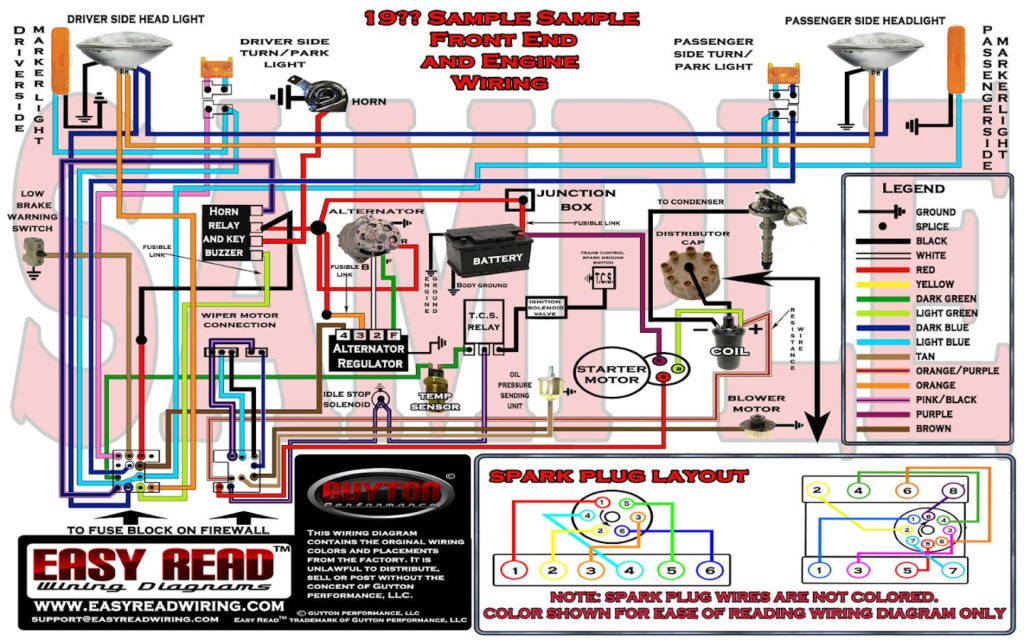
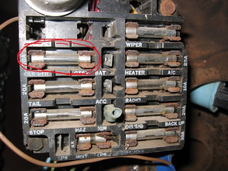
Ignition wiring diagrams show the various wires utilized to power the vehicle’s various components. Typically, there are four different colored terminals for each part. The accessories are colored red and the battery yellow the starter solenoid green. The “IGN” terminal lets you start your car, operate the wipers, and any other functions. This diagram shows how to connect ACC and ST terminals to the other components.
The terminal known as BAT is where the battery is connected. The electrical system is not able to begin without the battery. In addition the switch isn’t turned on. To locate your car’s battery look over your wiring diagram. The accessory terminals on your vehicle are connected to the battery and the ignition switch. The BAT Terminal is connected to the Battery.
Some ignition switches come with an additional “accessory position” that allows users to alter their outputs without the ignition. Some customers may prefer to utilize the auxiliary output independently of the ignition. To use the additional output, wire the connector with the same colors as the ignition, and connect it to the ACC terminal on the switch. While this is an excellent option, there’s an significant difference. The majority of ignition switches have an ACC position when the vehicle is in the ACC, but they’ll be at the START position when the car is in IGN.
Gallery of 1968 Camaro Ignition Coil Wiring Diagram
Gallery of 1968 Camaro Ignition Coil Wiring Diagram


