1969 Corvette Ignition Switch Wiring Diagram – Let’s start by looking at the different kinds of terminals that are found in an ignition switch. These terminals include the Ignition switch and Coil along with the Accessory. When we have a clear understanding of the purpose of each kind of terminal, we can then identify the various components of the ignition wiring. We will also discuss the functions of the Ignition switch and Coil. Following that, we’ll shift our attention to Accessory terminals.
Terminals for ignition switches
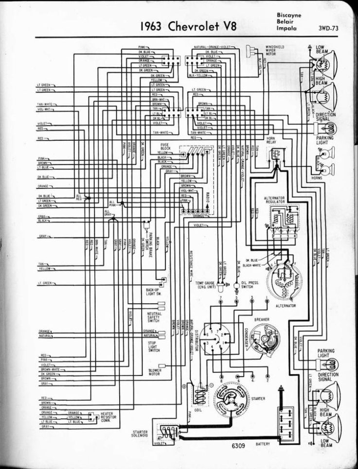
The ignition switch is comprised of three switches that supply the battery’s power to various locations. The first switch provides power to the choke whenever pushed, and the second is the position of the ignition switch’s ON/OFF. Different manufacturers use different color-coding systems that correspond to the conductors. OMC follows this procedure. A connector is also included inside the ignition switch to allow attaching an to a tachometer.
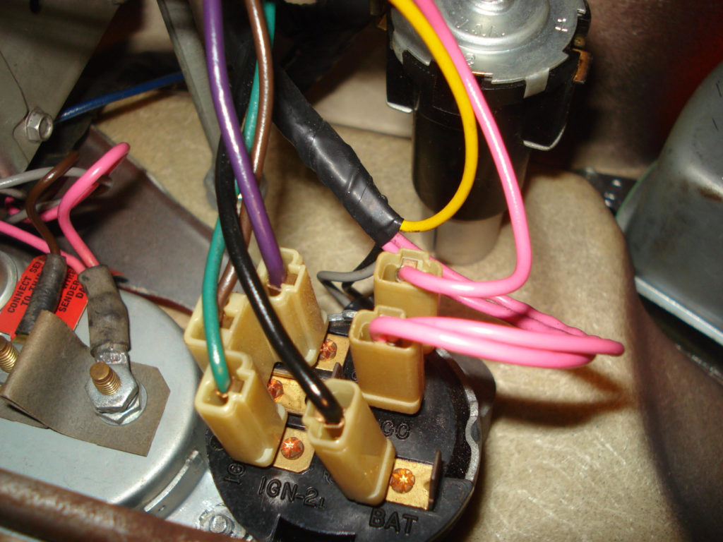
Even though most ignition switch terminals don’t carry an original number, they may be equipped with a different number. To make sure that the wires are plugged in to the switch, it is recommended to check their continuity. This can be accomplished with a simple multimeter. Once you’ve verified that the wires are in good condition, you can then install the connector. If your car is equipped with an original ignition switch supplied by the factory (or a wiring loom), the wiring loom might differ from the one in your car.
It is important to understand the ways in which the ACC outputs and the auxiliary outputs function to connect them. The ACC terminals as well as the IGN terminals function as the default connections to your ignition switch. The START and IGN connections are the most important connections for radio and stereo. The ignition switch switches the car’s engine ON and off. The terminals of older vehicles’ ignition switches are labeled by “ACC” and ST (for the individual magneto wires).
Terminals for coil
To identify the kind of ignition coil, the initial step is to understand the terminology. You’ll see a number of connections and terminals on a basic ignition wiring schematic which includes two primary and two secondary. The coils come with a distinct operating voltage. The initial step to determine which one you have will involve testing the voltage of S1 the main terminal. S1 should also undergo resistance tests to determine if it are a Type A or B coil.
The negative end of the chassis end should be connected to connect the coil’s low-tension side. This is also the ground on the diagram of ignition wiring. The high tension side provides positive power directly to the spark plugs. To reduce the noise the body of the coil is required to be connected to the chassis. But, it’s not required to connect electrically. The ignition wiring diagram will also reveal the connections between the positive and negative coil terminals. Sometimes, a damaged ignition coil can be identified by a scan done at an auto parts shop.
The black-and-white-striped wire from the harness goes to the negative terminal. The terminal that is negative is served by the black trace attached to the white wire. The contact breaker is linked to the black wire. You can take the black wire from the plug housing with a paper clip in case you are uncertain about the connection. Make sure the terminals aren’t bent.
Accessory terminals
Diagrams of ignition wiring depict the wires used to provide power to various components of the vehicle. Each component has four distinct connections that are color coded. To identify accessories, red stands for starter solenoid, yellow is for battery, and blue is for accessory. The “IGN” terminal allows you to start the car, manage the wipers or other operation features. The following diagram shows how to connect the ACC terminal and ST terminals to other components.
The terminal BAT is the connection to the battery. Without the battery, the electrical system does not start. A dead battery can cause the switch to not turn on. If you’re not sure of the location of your car’s battery situated, review the wiring diagram of your car to determine where it is. The accessory terminals of your car are connected to the battery and the ignition button. The BAT terminal is connected with the battery.
Certain ignition switches come with an accessory position where users can adjust their outputs as well as control them without the need to use the ignition. Sometimes, customers want to utilize an auxiliary output that is separate from the ignition. The auxiliary output can be connected by wiring the connector in the same color as your ignition, and then connecting it to the ACC terminal of the switch. This convenience feature is great however, there’s one distinction. The majority of ignition switches are set to be in an ACC position when the vehicle is in the ACC position, while they’re in the START position when the vehicle is in the IGN position.
Gallery of 1969 Corvette Ignition Switch Wiring Diagram
Gallery of 1969 Corvette Ignition Switch Wiring Diagram


