1969 Ford Thunderbird Ignition Wiring Diagram – Let’s first look at the different terminals on the ignition switch. These terminals are for the Ignition button, Coil and Accessory. Once we have identified which terminals are used, we can begin to identify the different components of the 1969 Ford Thunderbird Ignition Wiring Diagram. We will also discuss the roles of the Ignition switch and Coil. Then, we will focus on the accessory terminals.
Terminals for the ignition switch
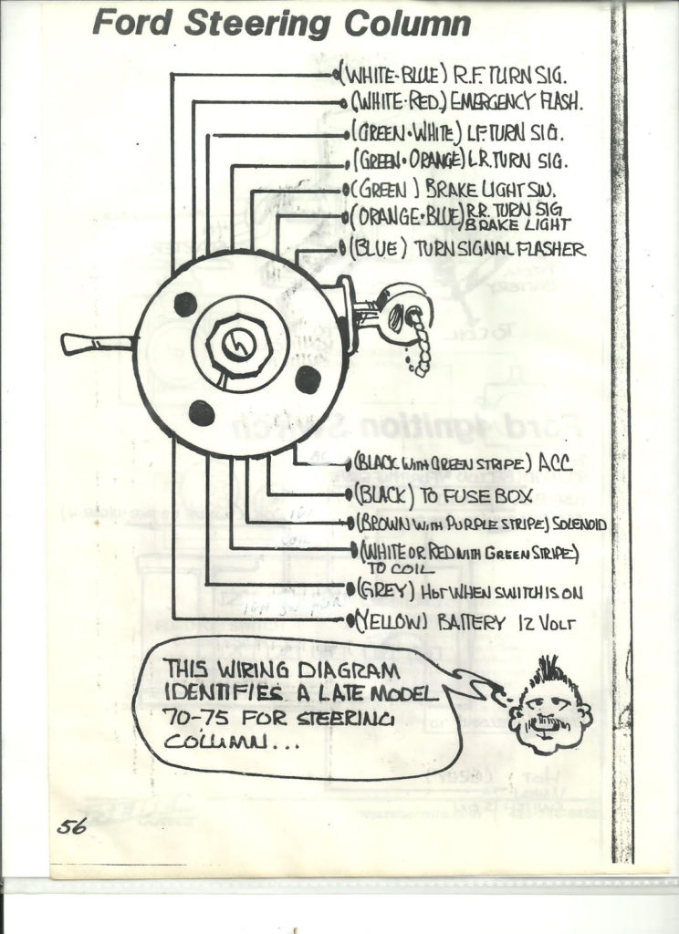
Three switches are found on the ignition switch. Each of the three switches transmits the battery’s current to several different destinations. The first switch is used to power the choke by pushing it, while the third switch is used to control the ON/OFF position. Every manufacturer has its individual color-coding system that we’ll go over in a separate article. OMC uses this system. The ignition switch also includes an adapter for the addition of an tachometer.
Although the majority of ignition switch terminals aren’t original, the numbering for each may not match the diagram. To ensure that your wires are properly plugged in to the ignition switch, you must verify their continuity. This can be done with a cheap multimeter. After you’re satisfied with the continuity then you can connect the new connector. If you are using an ignition switch that is supplied by the manufacturer the wiring loom will be distinct from the one that is you have in your car.
It is important to know the differences between the ACC and the auxiliary outputs. The ACC and IGN terminals are the default connections for the ignition switch. the START and IGN terminals are the primary connections for the stereo and radio. The ignition switch switches the engine of your car ON and off. The terminals of the ignition switch on older cars are labeled with the alphabets “ACC” as well as “ST” (for individual magneto wires).
Terminals for coil
Understanding the terminology is the first step in finding out what kind of ignition coil you’ve got. A basic diagram of the wiring will provide you with a range of terminals and connections. The operating voltage of each coil is different. It is important to first test the voltage at S1 (primary terminal). S1 should be examined for resistance to determine if the coil belongs to type A, B and/or C.
The coil’s low-tension end must be connected to the chassis positive. It is also the ground in an ignition wiring diagram. The high-tension side supplies positive direct to the sparkplugs. It is essential to suppress the body of the coil’s metal be connected to the chassis, however, it is not necessary. It is also possible to see the connections of the negative and positive coil’s terminals on the ignition wiring diagram. It is possible to find an issue with your ignition coil which can be identified by scanning it in an auto parts retailer.
The black-and-white-striped wire from the harness goes to the negative terminal. The other white wire is black-colored and connects to the terminal opposite. The black wire is connected to the contactbreaker. It is possible to check the connections with a paperclip to take the wires out of the housing. Make sure you verify that the connections have not been bent.
Accessory terminals
Diagrams of ignition wiring depict the wires used in the power supply of the vehicle. Each part has four distinct connections that are color coded. Accessories are red, the battery is yellow and the starter solenoid is green. The “IGN” terminal is used to start the vehicle and control the wipers and other operating functions. The diagram illustrates how you can connect ACC or ST terminals and the rest.
The terminal known as BAT is the location where the battery is. The electrical system cannot start without the battery. In addition, the switch will not begin to turn on. A wiring diagram can tell you where to find the battery of your car. The ignition switch is connected to the battery of your car. The BAT Terminal is connected to the battery.
Some ignition switches come with an additional “accessory position” that lets users alter their outputs without the ignition. Users may wish to use the auxiliary output in addition to the ignition. To make use of the auxiliary output, wire the connector in the same colors as the ignition, connecting it to the ACC terminal on the switch. This is a great convenience feature, but there is one distinction. Most ignition switches are set to be in an ACC position when the car is in the ACC position, while they’re in the START position when the car is in the IGN position.
Gallery of 1969 Ford Thunderbird Ignition Wiring Diagram
Gallery of 1969 Ford Thunderbird Ignition Wiring Diagram


