1969 Mustang Ignition Switch Wiring Diagram – We will first look at the various types and purposes of the terminals in the ignition switches. These terminals comprise the Ignition switch and Coil as well as the Accessory. After we’ve identified the terminals that are utilized and which ones are not, we can identify the different components of the 1969 Mustang Ignition Switch Wiring Diagram. We will also discuss the functions of the Ignition switch and Coil. We will then discuss the function of the ignition switch and Coil.
Ignition switch terminals
An ignition switch has three switches. They feed the battery’s voltage to different locations. The first switch is used to drive the choke through pushing it, and the second is for the ON/OFF setting. Each manufacturer has its individual color-coding system that we will discuss in another article. OMC uses this method. The ignition switch comes with an adapter for the addition of a Tachometer.
While the majority of ignition switch terminals do not have an original number, they may have a different number. Before you plug in the ignition switch, be sure to test the continuity. This can be checked with a multimeter that is inexpensive. When you’re satisfied with the integrity of the wires, then you’ll be able to install the new connector. The wiring loom of an ignition system switch that is supplied by the manufacturer is distinct.
It is important to know the differences between the ACC and auxiliary outputs. The ACC and IGN connectors are the standard connections of the ignition switch. While the START, IGN, and ACC terminals are the main connections to the radio or stereo, the START/IGN terminals are the most important ones. The ignition switch turns the engine of your car ON and off. The terminals of the ignition switch on older vehicles are marked with the initials “ACC” and “ST” (for the individual magneto wires).
Terminals for coil
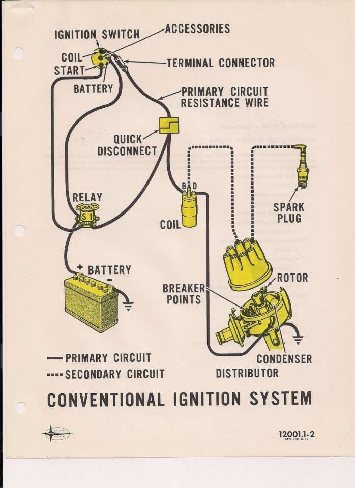
Understanding the terms is the first step towards determining which type of ignition coil you own. In a typical diagram of the wiring for ignition you’ll see several different connections and terminals, such as two primary and two secondary. Each coil operates at a specific voltage. The first step to determine the type you have is to check the voltage of S1 or the primary terminal. You should also test S1 for resistance to determine if it’s a Type A, B, or C coil.
The negative of the chassis must be connected to the low-tension side. It is also the ground in the diagram of ignition wiring. The high-tension component supplies the positive power direct to the spark plugs. The aluminum body of the coil has to be linked to the chassis to prevent it from being smothered but isn’t required. A wiring diagram can also illustrate the connection between the positive and negative coils. You may find an issue with your ignition coil which can be identified by scanning it in the auto parts shop.
The black-and-white-striped wire from the harness goes to the negative terminal. The positive terminal receives the white wire with the trace in black. The black wire connects to the contact breaker. To test the wires’ connections use a paperclip to lift them out of the housing. Make sure you don’t bend the connectors.
Accessory terminals
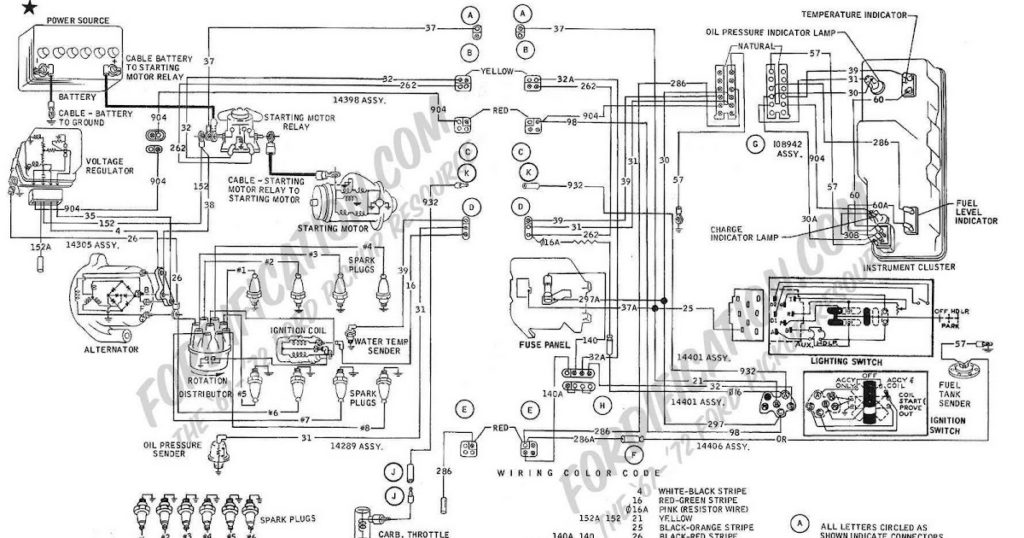
The wiring diagrams for the ignition show the different wires that power the various components of the vehicle. There are typically four different color-coded terminus for each component. Red stands for accessories, yellow for the battery, and green for the solenoid for starters. The “IGN” terminal can be used to start the car, turn on the wipers and other features. The following diagram shows how to connect the ACC terminal and ST terminals to various components.
The terminal BAT connects the battery to the charger. The electrical system won’t start in the event that the battery isn’t connected. In addition, the switch will not begin to turn on. You can view your wiring diagram to figure out where your car’s batteries are placed. The accessory terminals in your car connect to the battery and the ignition switch. The BAT Terminal is connected to the Battery.
Some ignition switches come with an additional position. This allows users to connect their outputs to a different place without the ignition. Users may wish to use the auxiliary output independently of the ignition. The auxiliary output is used to connect the connector with the same color as your ignition and attaching it to the ACC terminal of the switch. This feature is convenient however it does have one major difference. The majority of ignition switches are set to have an ACC position when the vehicle is in the ACC position, but they’re set to the START position when the vehicle is in the IGN position.
Gallery of 1969 Mustang Ignition Switch Wiring Diagram
Gallery of 1969 Mustang Ignition Switch Wiring Diagram


