1970 Vw Beetle Ignition Switch Wiring Diagram – In the beginning, we’ll look at the different types of terminals found in the ignition switch. These terminals comprise the Ignition switch, the Coil along with the Accessory. Once we know the purpose of each terminal, we can then identify the parts of the ignition wiring. We will also discuss what functions are available for the Ignition switch and the Coil. Then, we will turn our attention towards the accessories terminals.
The terminals of the ignition switch
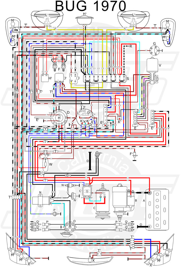
There are three different switches in an ignition switch, which transmit the battery’s current voltage to various destinations. The first switch provides power to the choke whenever it is pushed. The second is the position of the ignition switch’s ON/OFF. Each manufacturer has its own color-coding system, which we’ll discuss in a subsequent article. OMC follows this system. Connectors can be attached to the ignition switch to include a digital Tachometer.
Even though some of the ignition switch terminals could not be authentic, the numbering of the terminals may not be in line with the diagram. Check the electrical continuity first to ensure that they are correctly plugged in the ignition switch. This can be done with a cheap multimeter. When you’re happy with the quality of the connection it’s time to connect the new connector. The wiring loom used for an ignition switch that is supplied by the factory will be different from the one in your car.
Understanding how ACC outputs are connected to the other outputs inside your car is essential. The ACC, IGN and START terminals are the default connections to the ignition switch. They are also the main connections to the radio and stereo. The ignition switch is the one that turns the car’s engine on and off. On older vehicles the terminals of the ignition switch are identified with the letters “ACC”, and “ST” (for distinct magnet wires).
Terminals for coil
The language used to decide the kind and model of an ignition coil is the primary thing. The diagram of the basic ignition wiring illustrates a variety of connections and terminals. There are two primary and secondary connections. Each coil has an operating voltage. The first step to determine which type you have is to check the voltage at S1 or the primary terminal. S1 should be examined for resistance to identify if the coil is type A, B or C.
The coil’s low-tension side should be connected to the chassis’ less. This is the ground of the wiring for ignition. The high-tension side supplies positive direct to the spark plugs. The metal body of the coil needs to connect to the chassis to prevent it from being smothered however it isn’t electrically necessary. A wiring diagram can also illustrate the connection between the positive and negative coil terminals. Sometimes, a malfunctioning ignition coil can be detected through a scan performed at an auto parts shop.
The black-and-white-striped wire from the harness goes to the negative terminal. The positive terminal receives the white wire with an trace of black. The contact breaker is linked to the black wire. You can take the black wire from the plug housing with a paper clip If you’re unsure of the connections. Make sure you verify that the connections aren’t bent.
Accessory terminals
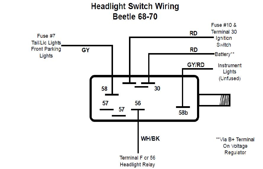
Diagrams of ignition wiring show the different wires that are utilized to power the vehicle’s various components. There are usually four colors-coded terminus of each part. For accessories, red is for starter solenoid, yellow is for battery and blue for accessories. The “IGN” terminal allows you to start the car, control the wipers or other operation features. The below diagram shows how to connect both the ACC terminal as well as the ST terminals to the other components.
The battery is attached to the terminal whose name is BAT. The electrical system cannot start without the battery. The switch will not turn on if there is no battery present. To locate your car’s battery look over your wiring diagram. The accessory terminals on your vehicle connect to the battery and the ignition switch. The BAT terminal connects to the battery.
Some ignition switches come with an independent “accessory” position, where users can control their outputs with no ignition. Sometimes, customers would like the output of the auxiliary to be used independently from the ignition. You can utilize the secondary input by connecting the connector to the ACC terminal. This is a great option, but there’s an important distinction. Many ignition switches have the ACC position when the car is in ACC mode and a START mode when it is in IGN.
Gallery of 1970 Vw Beetle Ignition Switch Wiring Diagram
Gallery of 1970 Vw Beetle Ignition Switch Wiring Diagram


