1973 Evinrude Ignition Switch Wiring Diagram – We’ll begin by looking at the various kinds of terminals that are found on the ignition switch. They include terminals for Coil, Ignition Switch, and Accessory. Once we’ve established the purpose of these terminals, it is possible to recognize the various parts of the ignition wiring. In addition, we will discuss the different functions of the Ignition Switch and Coil. Following that, we will proceed to the Accessory Terminals.
Terminals for ignition switch
The ignition switch has three switches. They feed the battery’s voltage to many different places. The first one supplies power to the choke when pushed, and the second is the switch that controls the ignition’s ON/OFF positions. Different manufacturers have their own color-coding system for different conductors which is documented in another article. OMC utilizes the same system. A connector can be added to the ignition switch to connect a digital tachometer.
Even though most ignition switch terminals don’t carry an original number, they might have a different one. Check the integrity of the wires to determine if they’re plugged into the ignition switch in the correct way. This can be accomplished using a simple multimeter. Once you are satisfied with the continuity of the wires you can install the new connector. If your car is equipped with an original ignition switch supplied by the factory (or wiring loom) the wiring loom will differ from that in your vehicle.
It is important to know the differences between the ACC and auxiliary outputs. The ACC terminals as well as the IGN terminals are the primary connections to your ignition switch. The START and IGN connections are the primary connections for radio and stereo. The ignition switch switches the car’s engine on and OFF. Older cars have the ignition switch terminals labeled “ACC” or “ST” (for individual magnetowires).
Terminals for coil
The first step to determine the type of ignition coil is to understand the terminology that is used. The basic ignition wiring diagram illustrates a variety of connections and terminals. There are two primary and one secondary. It is essential to identify the type of coil you own by examining the voltage on the primary terminal, called S1. To determine whether it’s a Type A, C, or B coil, it is recommended to also test S1’s resistance.
The coil’s low-tension component must be connected to the chassis positive. This is the ground in the wiring diagram for ignition. The high tension part supplies positive directly the spark plugs. For suppression purposes, the coil’s body metal is required to be connected to the chassis. This is not necessary to use electricity. There are also connections between the positive and negative coil’s terminals on the ignition wiring diagram. In certain instances it is possible to find a malfunctioned ignition coil is identified by scanning at an auto parts shop.
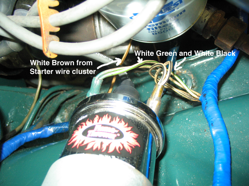
The black-and-white-striped wire from the harness goes to the negative terminal. The white wire is black-colored and connects to the terminal opposite. The black wire connects to the contact breaker. If you’re not certain about the connection between the twowires, use an old paper clip to take them from the plug housing. You should also check to ensure that the terminals aren’t bent.
Accessory terminals
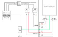
Diagrams of ignition wiring illustrate the wires that are used in the vehicle’s power supply. There are usually four different colors of terminals connected to each part. The accessories are red while the battery is yellow and the starter solenoid green. The “IGN terminal is used to start the vehicle, controlling the wipers, and for other functions. The diagram shows the connections between the ACC- and ST terminals.
The terminal BAT is the connector for the battery. The electrical system won’t start when the battery isn’t connected. In addition, the switch will not begin to turn on. It is possible to view your wiring diagram to determine the location of your car’s batteries. placed. The ignition switch and battery are connected by the accessory terminals. The BAT terminal is connected to the battery.
Some ignition switches feature the “accessory” position that allows users to regulate their outputs without having to use the ignition. Users may wish to use the auxiliary output in addition to the ignition. To make use of the auxiliary output, connect the connector using identical colors to the ignition and connect it to the ACC terminal on the switch. This feature of convenience is fantastic however, there’s one difference. Most ignition switches are configured to be in an ACC position when the vehicle is in the ACC position, but they’re in the START position when the vehicle is in the IGN position.
Gallery of 1973 Evinrude Ignition Switch Wiring Diagram
Gallery of 1973 Evinrude Ignition Switch Wiring Diagram