1978 Ford Ignition Wiring Diagram – We’ll begin by looking at the different types of terminals on an ignition switch. These include the terminals for the Ignition switch, Coil, and Accessory. When we have a clear understanding of the purpose of each kind of terminal, we can then identify the various components of the ignition wiring. We’ll also discuss the functions and the Coil. After that, we’ll turn our attention to the Accessory terminals.
The terminals of the ignition switch
There are three different switches on an ignition switch that transmit the battery’s current voltage to a variety of places. The choke is powered by the first switch. The second switch controls the ON/OFF switch of the ignition switch. Different manufacturers use different color codes for various conductors. This is described in another article. OMC uses the same method. There is a connector in the ignition switch to allow connecting an tachometer.
While the majority of ignition switch terminals don’t have an original number, they may have a different one. Check the continuity of all wires to ensure that they are properly plugged into the ignition switches. A multimeter is a great tool to check the continuity. After you’re happy with the continuity of your wires, you’ll be able to connect the new connector. If you are using a factory-supplied ignition switch the wiring loom will be different from that you have in your car.
It is important to know the differences between the ACC and the auxiliary outputs. The ACC and IGN connectors are the standard connections of the ignition switch. The START, IGN, and ACC terminals are primary connections for radios or stereo, the START/IGN connections are the most important ones. The ignition switch turns the engine of your car ON and off. Older cars are equipped with ignition switch terminals labeled “ACC” or “ST” (for individual magnetowires).
Terminals for coil
Understanding the terminology that is used is the first step in determining the kind of ignition coil you need. There are a variety of connections and terminals on the basic wiring diagram for ignition, including two primary, and two secondary. Each coil is equipped with a distinct operating voltage. To determine which type of coil you’ve got first, you need to check the voltage at S1, which is the primary terminal. It is also recommended to check S1 for resistance in order to identify if it’s an A, B, or C coil.
The chassis’ negative end should be connected to the coil’s low-tension side. It is also the ground on the diagram of ignition wiring. The high-tension part supplies the spark plugs with positive. It is necessary to suppress the metallic body of the coil is connected to its chassis, but not essential. The wiring diagram for ignition will also outline the connection of the positive coil’s terminals. In certain instances scanning your local auto parts shop will be able to diagnose the malfunctioning ignition coils.
The black-and-white-striped wire from the harness goes to the negative terminal. The other white wire has a black trace on it, and it goes to the positive terminal. The contact breaker is connected to the black wire. You can examine the connections with a paperclip to remove the wires of the housing. Check that you don’t bend the connectors.
Accessory terminals
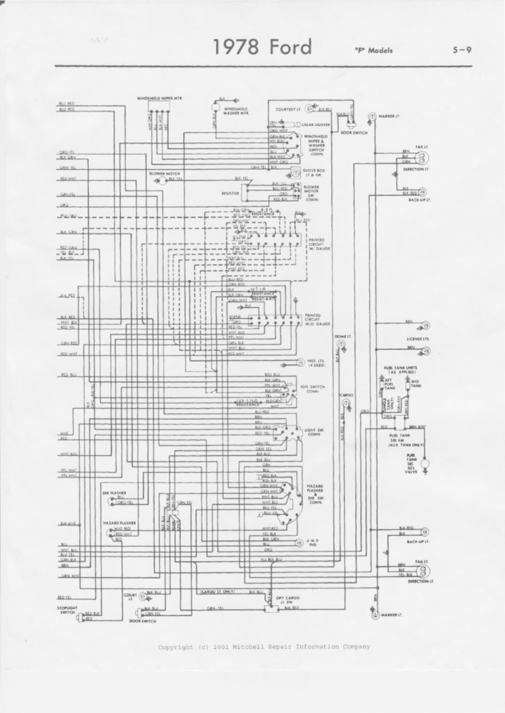
The wiring diagrams for the ignition show the different wires used to are used to power various components of the car. There are usually four different colors of terminals connected to each part. The accessories are red and the battery yellow, and the starter solenoid green. The “IGN” terminal is used to start the vehicle, controlling the wipers and various other functions. The diagram illustrates how to connect ACC or ST terminals and the rest.
The terminal BAT holds the battery. The electrical system cannot start without the battery. Additionally, the switch won’t begin to turn on. A wiring diagram can inform you the location of your car’s battery. The accessory terminals in your car are connected to the ignition switch as well as the battery. The BAT Terminal is connected to the Battery.
Some ignition switches come with an additional “accessory” position, where users can manage their outputs without the ignition. Sometimes, customers wish to make use of an auxiliary output that is separate from the ignition. The auxiliary output can be utilized by wiring the connector with the same colors as your ignition and attaching it to the ACC terminal of the switch. This feature of convenience is fantastic however, there’s one difference. A majority of ignition switches feature the ACC position when the car is in ACC mode, and a START position when you are in IGN.
Gallery of 1978 Ford Ignition Wiring Diagram
Gallery of 1978 Ford Ignition Wiring Diagram


