1978 International Scout Ignition Wiring Diagram – We will first take a look at the different kinds of terminals for the ignition switch. These are the terminals for the Ignition, Coil, or Accessory. Once we have established what these types of terminals are for, we will proceed to discover the various components of the 1978 International Scout Ignition Wiring Diagram. We’ll also discuss the functions of the Ignition switch, as well as the Coil. Then we’ll move on to the Accessory Terminals.
Terminals for ignition switches
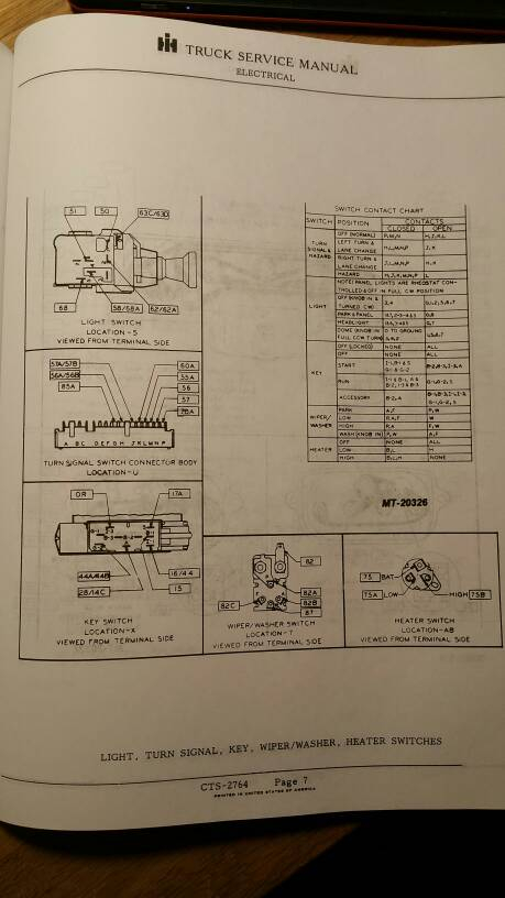
There are three separate switches in an ignition switch, which feed the battery’s voltage to various locations. The first switch provides power to the choke, while the second switch controls the on/off state of the switch. Different manufacturers have different color-coding schemes to identify different conductors. We’ll discuss this in another article. OMC uses the same method. Connectors can be attached to the ignition switch to add an electronic tachometer.
Even though the majority of ignition switch terminals don’t appear in their original configuration however, the numbers may not be in line with the diagram. Check the integrity of the wires first to make sure they are correctly plugged in the ignition switch. This can be checked using an inexpensive multimeter. Once you are satisfied that all wires are in good order and you are able to connect the new connector. If your car has an original factory-supplied ignition switch (or wiring loom), the wiring loom may differ from that in your vehicle.
First, understand the differences between ACC and the auxiliary outputs. The ACC and IGN terminals are the default connections for your ignition switch. the START and IGN terminals are the principal connections to the radio and stereo. The ignition switch is responsible for turning the engine of your car to and off. Older vehicles are identified with the letters “ACC”, “ST”, (for individual magneto cables) at their ignition switch terminals.
Terminals for coil
To identify the kind of ignition coil, the initial step is to learn the terminology. In a simple diagram of the wiring for ignition you’ll see a number of different connections and terminals, which include two primary and two secondary. The coils are equipped with a particular operating voltage, and the first step to determine which one you have will involve testing the voltage at S1, the primary terminal. To determine if it is an A, C or B coil you must also check the resistance of S1.
The chassis’ negative needs to be connected to the low-tension side. This is the base of the ignition wiring. The high tension side provides positive power directly to the spark plugs. The metal body of the coil needs to connect to the chassis to suppress the effect but is not electrically essential. You will also see the connections between the positive and the negative coil terminals on the ignition wiring diagram. Sometimes, a malfunctioning ignition coil is identified by a scan done at an auto parts shop.
The black-and-white-striped wire from the harness goes to the negative terminal. The white wire is the other one. It is black with a trace, and it connects to the positive terminal. The black wire connects to the contact breaker. You can remove the black wire from the housing of the plug by using a paperclip in case you are uncertain about the connection. Also, make sure to verify that the connections aren’t bent.
Accessory terminals
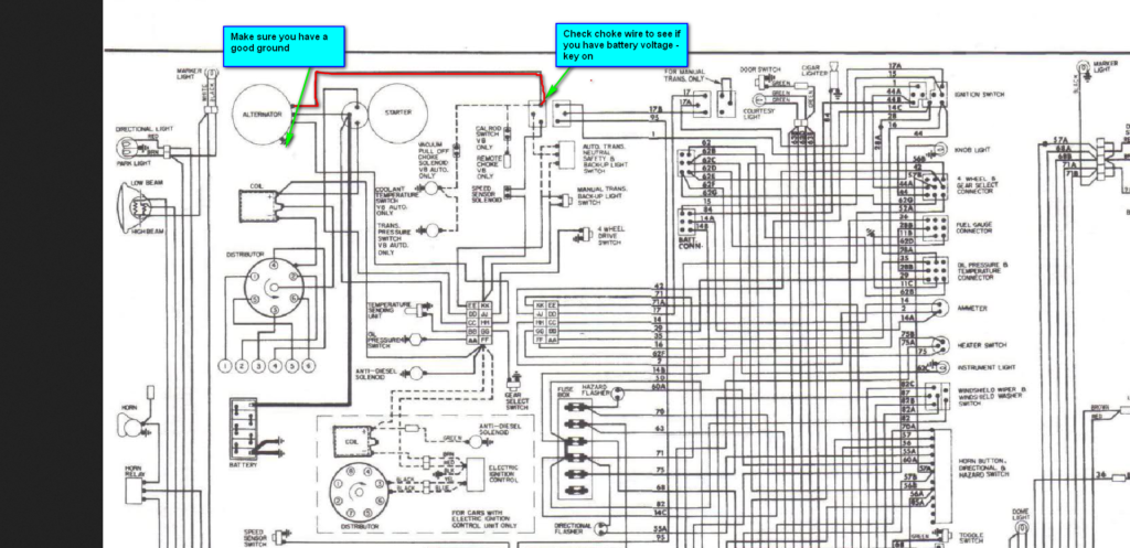
Diagrams of ignition wiring show the wires that are used to power the vehicle’s electrical supply. There are usually four colored terminals that correspond to the respective component. To identify accessories, red is the starter solenoid’s color, yellow for battery, and blue is for accessory. The “IGN” terminal is used to start the car and operate the wipers and other operating features. This diagram shows how you can connect ACC and ST terminals with the rest of components.
The terminal BAT is the connection to the battery. The electrical system is not able to begin without the battery. In addition the switch won’t come on. You can refer to your wiring diagram if you are not sure where the batteries of your car are located. The accessory terminals in your car connect to the ignition switch as well as the battery. The BAT terminal is connected to the battery.
Certain ignition switches have an additional position. This allows users to access their outputs from a different place without the ignition. Sometimes, customers want to utilize the auxiliary output separate from the ignition. You can use the auxiliary output by connecting it to an ACC terminal on your switch using the same colors. While this is a convenient feature, there is one significant difference. Most ignition switches are designed to show an ACC status when the car’s in the ACC or START positions.
Gallery of 1978 International Scout Ignition Wiring Diagram
Gallery of 1978 International Scout Ignition Wiring Diagram


