1983 Ford F150 Ignition Wiring Diagram – Let’s start by looking at the different types of terminals on the ignition switch. These are terminals that are used for Coil, Ignition Switch, and Accessory. Once we know the purpose of each type of terminal, we can then identify the parts of the ignition wiring. In addition, we will discuss the different functions of the Ignition Switch and Coil. Next, we’ll discuss the roles of the Ignition switch and Coil.
Terminals for ignition switches
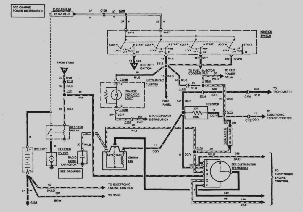
The ignition switch consists of three switches. They are responsible for supplying the battery’s power to several places. The first switch supplies power to the choke, and the third switch toggles the ON/OFF state of the switch. Each manufacturer has their own color-coding system, which we will discuss in another article. OMC utilizes this procedure. The ignition switch comes with an adapter for the addition of the tachometer.
Although many ignition switch terminals don’t come in original form however, the numbers may not be in line with the diagram. Verify the continuity of the wires first to make sure they are correctly plugged in the ignition switch. A multimeter is an excellent instrument to verify the continuity. Once you are satisfied that the wires are in good continuity and you are able to connect the new connector. If you are using a factory-supplied ignition switch the wiring loom will be different from that you have in your car.
For connecting the ACC outputs to the auxiliary outputs on your car, you need first know how these two connections work. The ACC terminals and IGN terminals serve as the standard connections for your ignition switch. The START and IGN connections are the primary connections for stereo and radio. The ignition switch is the engine’s on/off button. Older cars are identified by the initials “ACC”, “ST”, (for individual magneto cables) at the ignition switch’s terminals.
Terminals for coil
The first step to determine the kind of ignition coil is to know the terms employed. The basic ignition wiring diagram illustrates a variety of connections and terminals. There are two primary and one secondary. Each coil has an operating voltage. The first step in determining which kind you’re using is to examine the voltage of S1 or the primary terminal. It is also recommended to test S1 for resistance to identify if it’s a Type A, B, or C coil.
The chassis’ negative end should be connected to the coil’s low-tension side. This is the base of the ignition wiring. The high-tension end supplies positive direct to the sparkplugs. The aluminum body of the coil needs to be linked to the chassis for suppression but isn’t required. There are also connections of the positive and the negative coil’s terminals on an diagram of the ignition wiring. You may find an issue with your ignition coil that is easily identified by scanning it in an auto parts retailer.
The black-and-white-striped wire from the harness goes to the negative terminal. The positive terminal receives the other white wire, which has a black trace. The black wire is connected to the contactbreaker. It is possible to check the connections with a paperclip to take the wires out of the housing. Make sure you don’t bend the connectors.
Accessory terminals
The diagrams for ignition wiring depict the wires that are used in the power supply of the vehicle. Typically there are four distinct color-coded terminals for each component. For accessories, red stands the starter solenoid’s color, yellow is for battery, and blue is for accessory. The “IGN” terminal is used to turn on the car, control the wipers, and other features. This diagram demonstrates how to connect ACC and ST terminals with the other components.
The terminal BAT connects the battery to the charger. The electrical system cannot begin without the battery. The switch won’t turn on if there is no battery present. If you’re not sure of where your car’s battery is situated, you can review your wiring diagram to see the best way to find it. The accessory terminals of your car are connected to the battery and ignition button. The BAT connector is connected to the battery.
Some ignition switches are equipped with an additional position. This lets users access their outputs from a different place without the ignition. Sometimes, customers may wish to use the auxiliary input independently of the ignition. In order to use the additional output, wire the connector using identical colors to the ignition, connecting it to the ACC terminal on the switch. This convenience feature is great however, there’s one differentiator. Most ignition switches are configured to operate in the ACC position when the car is in the ACC position, but they’re in the START position when the car is in the IGN position.
Gallery of 1983 Ford F150 Ignition Wiring Diagram
Gallery of 1983 Ford F150 Ignition Wiring Diagram


