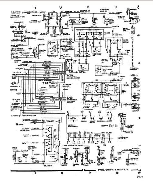
1984 Ford F150 Ignition Switch Wiring Diagram – We will first look at the various types of terminals on the ignition switch. These are terminals for the Ignition, Coil, or Accessory. After we’ve established the purpose of these terminals are We will then discover the various components of the 1984 Ford F150 Ignition Switch Wiring Diagram. Then, we will discuss the functions as well as the Coil. We’ll then turn our attention to the accessory terminals.
Terminals for ignition switch
The ignition switch has three switches. They supply the voltage of the battery to many different places. The ON/OFF setting of the switch that controls the ignition is managed by the third switch, which supplies power to the choke whenever it is pushed. Different manufacturers have different color codes for different conductors. This is discussed in another article. OMC follows this method. An adapter is included on the ignition switch, allowing the installation of an tonometer.
Although some ignition switch terminals might not be original, the numbers of the terminals may not match the diagram. You should first check the electrical continuity to see if they are plugged into the correct ignition switch. This can be done with a multimeter that is inexpensive. Once you are satisfied with the integrity of the wires it is time to install the new connector. The wiring loom of an ignition switch that is supplied by the manufacturer will differ from the one you have in your car.
The first step is to understand the distinctions between ACC and secondary outputs. The ACC terminals and IGN terminals serve as the standard connections for the ignition switch. The START and IGN connections are the main connections for stereo and radio. The ignition switch is the one that turns the engine of your car to and off. Older cars are identified with the letters “ACC”, “ST”, (for individual magneto cables) on their ignition switch’s terminals.
Terminals for coil
To figure out the type of ignition coil, the initial step is to understand the definition of. In a typical diagram of the wiring for ignition, you will see various connections and terminals, such as two primary and two secondary. The operating voltage of every coil is different. It is important to first test the voltage at S1 (primary terminal). S1 should also be checked for resistance to determine if the coil is a Type B, B or A coil.
The coil with low tension must be connected at the chassis’s minus. This is the wiring diagram you will see in the diagram of wiring. The high-tension end supplies positive direct to the sparkplugs. To prevent noise the body of the coil must be connected to the chassis. But, it’s not necessary to connect the coil electrically. The wiring diagram for ignition will also outline how to connect the positive coil terminals. You may find an issue with the ignition coil that can be easily diagnosed by scanning it in an auto parts store.
The black-and-white-striped wire from the harness goes to the negative terminal. The positive terminal is connected to the white wire with the trace of black. The contact breaker is linked to the black wire. To check the connection, use a paperclip or a pencil to remove them of the housing for the plug. Be sure the terminals don’t bend.
Accessory terminals
Diagrams of ignition wiring show the wires that are used in the vehicle’s power supply. Each part has four distinct color-coded connections. The accessories are colored red and the battery yellow and the starter solenoid is green. The “IGN terminal” is used to run the wipers, and other operating functions. The diagram below shows how to connect the ACC terminal and ST terminals to the other components.
The terminal BAT is the connection to the battery. Without the battery, the electrical system does not get started. Additionally the switch isn’t turned on. If you’re not sure of the exact location where the battery in your car is situated, review the wiring diagram of your car to determine the best way to find it. The accessory terminals in your car are connected to the battery and the ignition button. The BAT Terminal is connected to the Battery.
Some ignition switches are equipped with an accessory position. This allows users to connect their outputs to a different location without having to turn on the ignition. Sometimes, customers would like the auxiliary output to be operated independently of the ignition. You can use the secondary input by connecting the connector to the ACC terminal. While this is a convenient option, there’s an significant difference. Most ignition switches will have an ACC position when the vehicle is in the ACC however they’ll be at the START position if the car is in IGN.
Gallery of 1984 Ford F150 Ignition Switch Wiring Diagram
Gallery of 1984 Ford F150 Ignition Switch Wiring Diagram


