1984 Ford F150 Ignition Wiring Diagram – We will first look at the different types of terminals in the ignition switch. These terminals comprise the Ignition switch as well as the Coil as well as the Accessory. Once we have identified the terminals used, we can begin to identify the different components of the 1984 Ford F150 Ignition Wiring Diagram. Then, we will discuss what functions are available for the Ignition switch, as well as the Coil. After that, we will concentrate on the accessories terminals.
Terminals for the ignition switch
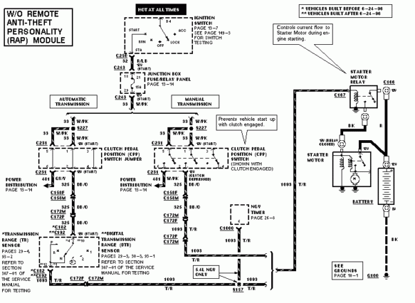
Three switches are located on the ignition switch. Each of these three switches transmits the battery’s current to various locations. The first is used to turn on the choke by pushing it, while the second is for the ON/OFF position. Every manufacturer has its unique color-coding system, which we’ll go over in a separate article. OMC utilizes this procedure. This connector allows the attachment of a speedometer the ignition switch.
While the majority of ignition switch terminals don’t have the original design The numbering might not match the diagram. Before plugging in the ignition switch, be sure to test the continuity. This can be done with an inexpensive multimeter. Once you are satisfied with the integrity of the wires connect the new connector. If you’re using an ignition switch supplied by the manufacturer, the wiring loom is different from that you have in your car.
For connecting the ACC outputs to the auxiliary outputs of your vehicle, you have to understand the way these two connections function. The ACC, IGN and START terminals are the primary connection to the ignition switch. They are also the primary connections to the radio and stereo. The ignition switch’s function is to turn the car’s engines on and off. Older cars are identified with the letters “ACC”, “ST”, (for individual magneto cables) at the ignition switch’s terminals.
Terminals for coil
Understanding the terms is the initial step to knowing what type of ignition coil you’ve got. You will see several connections and terminals in a basic ignition wiring schematic which includes two primary as well as two secondary. You must determine the type of coil you own by examining the voltage at the primary terminal, S1. S1 should be tested for resistance in order to identify if the coil belongs to type A, B or C.
The negative end of the chassis must be connected to the coil’s low-tension end. This is also the ground in the wiring diagram for ignition. The high-tension side supplies positively directly to the spark plugs. The body of the coil has to connect to the chassis to suppress the effect, but it is not electrically necessary. The wiring diagram for the ignition will explain how to connect the two terminals of the positive or negative coils. Sometimes, a visit to an auto parts shop can identify a problem with the ignition wire.
The black-and-white-striped wire from the harness goes to the negative terminal. The white wire is black and goes to the negative terminal. The black wire is connected to the contact breaker. It is possible to remove the black wire from the housing of the plug by using a paperclip in case you are uncertain about the connections. Make sure you don’t bend the connectors.
Accessory Terminals
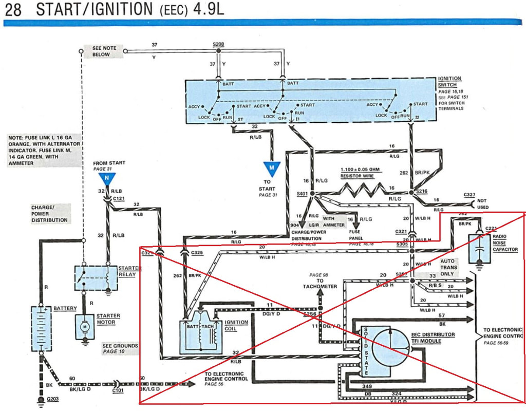
The diagrams for ignition wiring depict the wiring used in the vehicle’s power supply. There are typically four color-coded terminals to each component. Red stands for accessories, yellow represents the battery and green is for the solenoid for starters. The “IGN terminal” is used to provide power to the wipers and other operating features. The diagram illustrates how to connect ACC or ST terminals as well as the rest.
The terminal BAT is the connection for the battery. The electrical system will not start without the battery. The switch also won’t turn on without the battery. To find the battery in your car, check your wiring diagram. Your car’s accessory terminals are connected to the ignition switch, as well as the battery. The BAT Terminal is connected to the Battery.
Some ignition switches come with an accessory position. This lets users connect their outputs to a different location without having to turn on the ignition. Some customers may prefer to use the auxiliary output independently of the ignition. In order to use the auxiliary output, connect the connector in the same colors as the ignition, and connect it to the ACC terminal on the switch. This feature is convenient, but it has one major distinction. Most ignition switches will be in an ACC position when the vehicle is in ACC however, they will be in the START position if the car is in IGN.
Gallery of 1984 Ford F150 Ignition Wiring Diagram
Gallery of 1984 Ford F150 Ignition Wiring Diagram


