1985 Chevy Truck Ignition Switch Wiring Diagram – First, we will take a look at the different kinds of terminals that are used on the ignition switch. These terminals comprise the Ignition switch as well as the Coil as well as the Accessory. Once we know the purpose of these terminals and what they do, we can then be able to identify the various parts of the ignition wiring. In addition, we will discuss the roles of the Ignition switch, and Coil. Then we’ll proceed to the Accessory Terminals.
Terminals for ignition switch
An ignition switch contains three separate switches that feed the battery’s current to different destinations. The first switch is the one that supplies the choke with power, while the second switch controls the state of the switch. Different manufacturers use different colors for different conductors. This is described in another article. OMC uses this method. The ignition switch is also equipped with an option to connect the timer.
Although most ignition switch terminals can be duplicated, the numbers might not be in line with the diagram. You should first check the integrity of the wires to ensure that they are connected to the ignition switch correctly. You can check this using an inexpensive multimeter. Once you are satisfied with the continuity of the wires it is time to connect the new connector. If your car has an installed ignition switch the wiring diagram will differ.
Understanding how the ACC outputs connect to the auxiliary outputs in your car is vital. The ACC/IGN terminals function as the default connection on the ignition switch. The START/IGN terminals are connected to the stereo or radio. The ignition switch switches the engine of your car ON and OFF. On older vehicles the terminals of the ignition switch are marked with the letters “ACC” and “ST” (for the individual magnet wires).
Coil terminals
The terms used to define the kind and model of an ignition coil is the primary thing. The basic ignition wiring diagram illustrates a variety of connections and terminals. There are two primary and one secondary. The coils come with a distinct operating voltage, and the first method of determining what type you have will involve testing the voltage of S1 the primary terminal. S1 must also be inspected for resistance to determine if it’s an A, Type B, or A coil.
The coil with low tension must be connected to the chassis’s plus. This is the ground in the wiring diagram for ignition. The high-tension part is a positive connection to the sparkplugs. For suppression purposes, the coil’s body metal must be connected to the chassis. It’s not necessary to use electricity. It is also possible to see the connections between the positive and the negative coil’s terminals on the diagram of the ignition wiring. Sometimes, an inspection at an auto part store can detect a defective ignition wire.
The black-and-white-striped wire from the harness goes to the negative terminal. The other white wire is black-colored and goes to the terminal opposite. The contact breaker is attached to the black wire. To confirm the connections, you can use a paperclip or a pencil to remove them of the housing for the plug. Also, see that the terminals are not bent.
Accessory Terminals
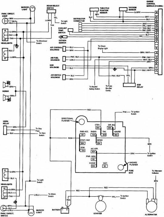
Diagrams of ignition wiring show the various wires utilized for powering the different components. Typically there are four colors-coded terminals that are used for each component. Red stands for accessories, yellow is for the battery and green for the starter solenoid. The “IGN” terminal is utilized to turn on the car, operate the wipers, and other features. The diagram shows how to connect the ACC and ST terminals to the other components.
The terminal BAT holds the battery. Without the battery the electrical system will not get started. Furthermore the switch won’t come on. If you’re not sure where your car’s battery is situated, you can examine your wiring diagram to figure out how to locate it. The accessory terminals in your car are connected to the battery as well as the ignition switch. The BAT terminal is connected with the battery.
Certain ignition switches have an accessory position where users can modify their outputs and manage them without the need to use the ignition. Sometimes, users want to make use of an additional output that is not connected to the ignition. The auxiliary output could be connected to connect the connector with the same colors as the ignition, and then attaching it to the ACC terminal of the switch. This is an excellent feature, but there is an important distinction. Most ignition switches are designed to display an ACC status when the vehicle is at the ACC or START position.
Gallery of 1985 Chevy Truck Ignition Switch Wiring Diagram
Gallery of 1985 Chevy Truck Ignition Switch Wiring Diagram


