1985 Jeep Cj7 Ignition Wiring Diagram – The first step is to take a look at the different types of terminals on the ignition switch. These are the terminals for the Ignition, Coil, or Accessory. Once we know the purpose of each kind of terminal, we can then determine the components of the ignition wiring. In addition, we will discuss the function of the Ignition switch and Coil. We will then discuss the functions of the Ignition switch as well as Coil.
Terminals for the ignition switch
There are three separate switches on the ignition switch, and they provide the battery’s voltage to various destinations. The first is used to drive the choke through pushing it, and the second is for the ON/OFF position. Different manufacturers utilize their own color-coding method for the different conductors, that is described in a separate article. OMC utilizes the same system. Connectors can be attached to the ignition switch to include an electronic Tachometer.
Even though some of the ignition switch terminals could not be original, the numbers of each one might not match the diagram. Before plugging into the ignition switch make sure to check the continuity. This can be accomplished using a simple multimeter. When you’re satisfied that all wires are in good continuity then you can connect the new connector. If your vehicle has an original ignition switch supplied by the factory (or wiring loom) the wiring loom will differ from that in your car.
Understanding how ACC outputs are connected to the auxiliary outputs in your car is essential. The ACC and IGN terminals are the default connections on the ignition switch. the START and IGN terminals are the main connections to the radio and stereo. The ignition switch operates the engine’s switch to turn off or on. The terminals of older vehicles ignition switches are marked by “ACC” as well as ST (for the individual magneto wires).
Coil terminals
To figure out the type of ignition coil, the initial step is to understand the terms. A basic ignition wiring diagram will display a range of terminals and connections which include two primary terminals and two secondary. The coils come with a distinct operating voltage. The first method of determining what type you’ve got is to check the voltage of S1 the main terminal. To determine if the coil is an A, C, or B coil it is recommended to also test S1’s resistance.
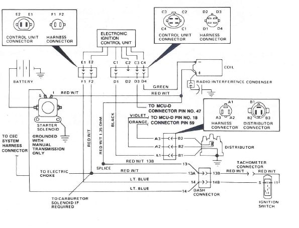
The coil’s low-tension end must be connected with the chassis’ positive. This is what’s called the ground on the ignition wiring diagram. The high-tension part supplies the spark plugs with positive. For suppression purposes the body of the coil is required to be connected to the chassis. However, it is not necessary to connect the coil electrically. The wiring diagram of the ignition will explain how to connect the two terminals of the negative or positive coils. Sometimes, a visit to an auto part store can diagnose a malfunctioning ignition wire.
The black-and-white-striped wire from the harness goes to the negative terminal. The white wire is the other one. It has a black trace on it, and connects to the positive terminal. The contact breaker is attached to the black wire. You can examine the connections with a pencil to remove the wires from the housing. Check that the terminals aren’t bent.
Accessory Terminals
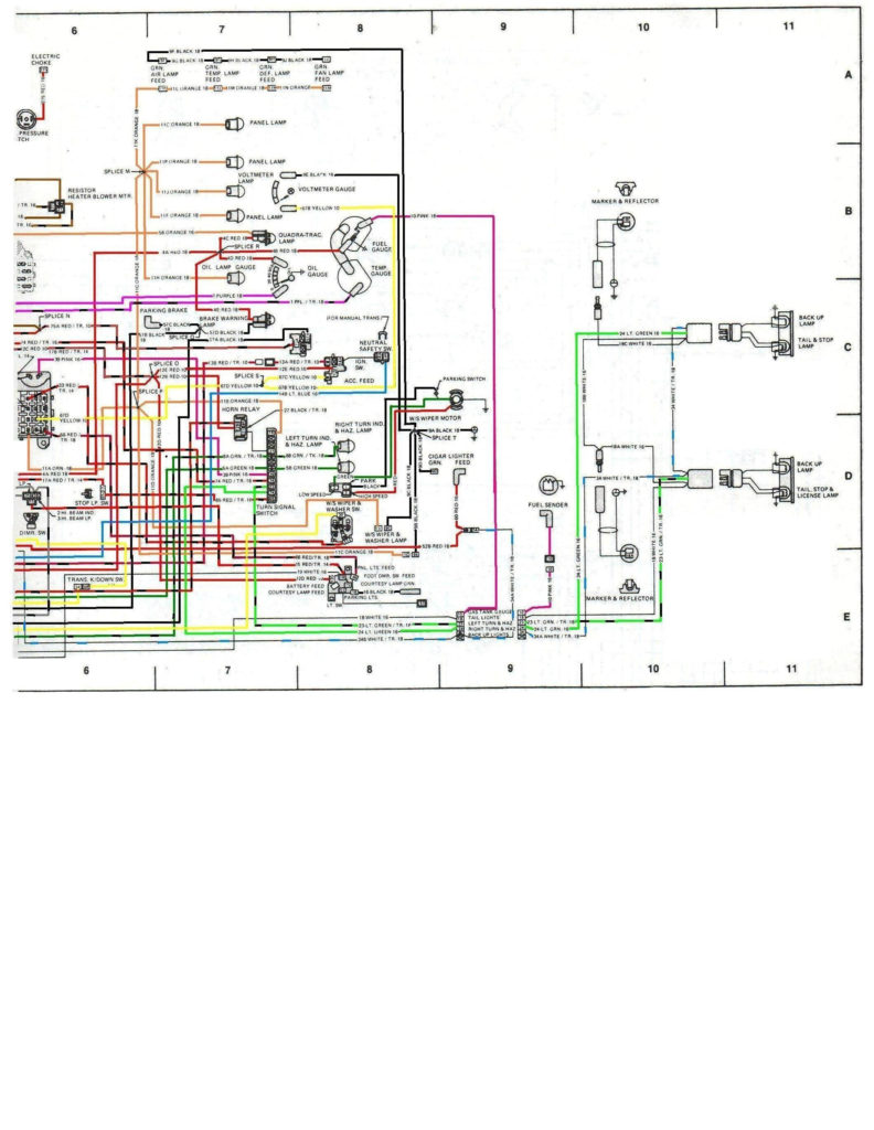
The diagrams for ignition wiring depict the wires that are used in the vehicle’s power supply. In general there are four distinct colored terminals for each part. The red color represents accessories, yellow is for the battery, and green for the solenoid for starters. The “IGN terminal allows you to start the car, control the wipers, or any other operation features. The diagram shows how to connect the ACC and ST terminals to the other components.
The terminal BAT connects the battery to the charger. The battery is necessary for the electrical system to start. Additionally, the switch will not turn on without the battery. It is possible to look up your wiring diagram to determine where the batteries of your car are placed. The ignition switch as well as the battery are connected via accessory terminals. The BAT terminal connects to the battery.
Some ignition switches feature an independent “accessory” location, which allows users can control their outputs with no ignition. Sometimes, customers want to utilize an auxiliary output that is separate from the ignition. The auxiliary output could be used by wiring the connector in the same colors as your ignition and attaching it to the ACC terminal of the switch. This option is useful however it does have one key differentiator. Most ignition switches are configured to operate in the ACC position when the vehicle is in the ACC position, while they’re in the START position when the vehicle is in the IGN position.
Gallery of 1985 Jeep Cj7 Ignition Wiring Diagram
Gallery of 1985 Jeep Cj7 Ignition Wiring Diagram


