1986 Alfa Romeo Spider Ignition Coil Wiring Diagram – The first step is to look at the different terminals on the ignition switch. They include terminals for the Ignition switch, Coil, and Accessory. Once we know the purpose of each type of terminal, it is possible to identify the various components of the ignition wiring. We’ll also go over the functions for the Ignition switch as well as the Coil. Following that, we’ll shift our attention to Accessory terminals.
Terminals for the ignition switch
An ignition switch contains three separate switches that feed the battery’s current to different locations. The first switch provides power to the choke when it is pushed. The second is the ignition switch’s ON/OFF position. Each manufacturer has its individual color-coding system that we will discuss in another article. OMC employs this system. The connector allows for the attachment of a speedometer to the ignition switch.
Although the majority of ignition switch terminals may not be original, the numbering for each one may not be in line with the diagram. First, check the continuity of each wire to ensure they are correctly plugged into the ignition switches. This can be accomplished with a multimeter that is inexpensive. Once you’re satisfied about the continuity of the wires, then you’ll be able to install the new connector. If your vehicle has an original factory-supplied ignition switch (or an electrical loom) The wiring loom may differ from the one in your vehicle.
Understanding how the ACC outputs are connected to the auxiliary outputs inside your car is essential. The ACC, IGN and START terminals are the default connections to the ignition switch. They also function as the primary connections to the radio and stereo. The ignition switch regulates the engine in your car. In older vehicles, the ignition switch terminals are marked with the initials “ACC”, and “ST” (for the individual magnetic wires).
Terminals for coil
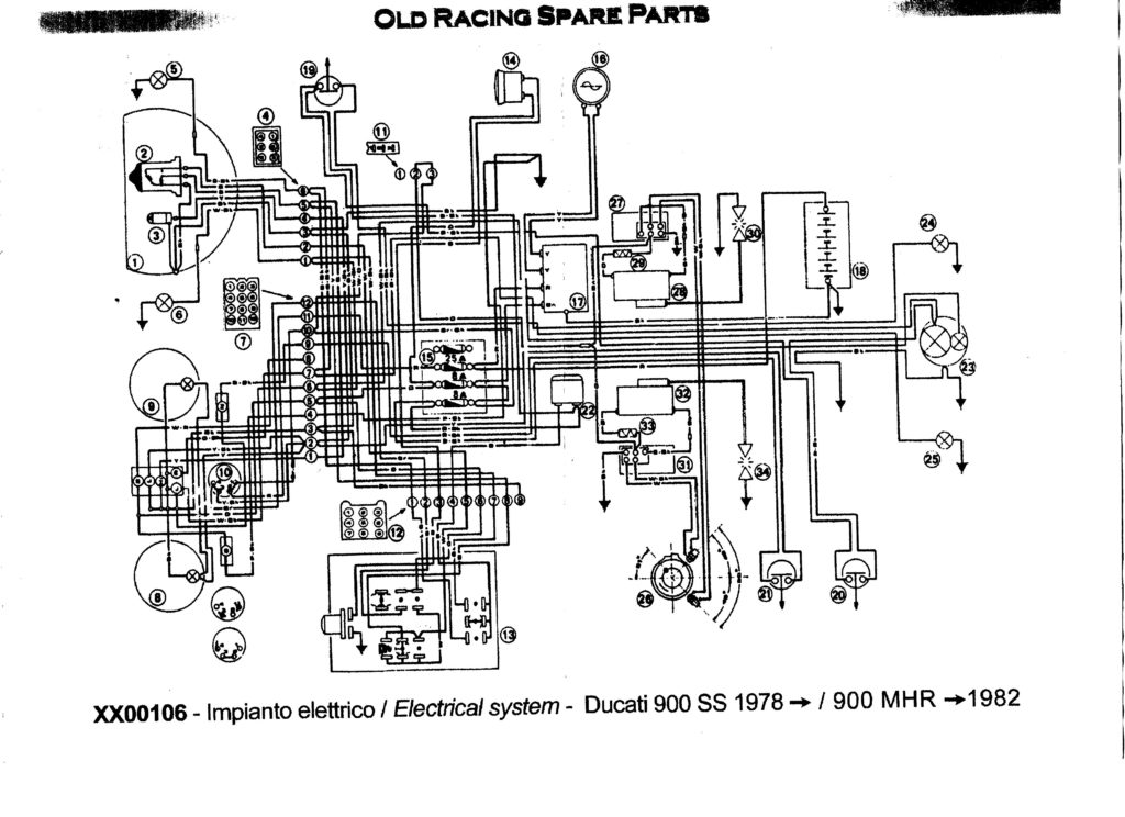
To figure out the type of ignition coil, the first step is to understand the definition of. A basic ignition wiring diagram will show a variety of terminals and connections, which include two primary terminals and two secondary. You need to determine the type of coil you own by examining the voltage at the primary terminal, S1. S1 must be tested for resistance in order to identify if the coil belongs to type A, B and/or C.
The coil’s low-tension end must be connected to the chassis positive. This is what is known as the ground for the ignition wiring. The high tension side supplies positive directly the spark plugs. The metal body of the coil needs to be connected to the chassis for suppression purposes, but it is not electrically essential. The wiring diagram for ignition will also show the connections of the positive coil terminals. Sometimes, a visit to an auto part store can detect a defective ignition wire.
The black-and-white-striped wire from the harness goes to the negative terminal. The white wire is black-colored and goes to the terminal opposite. The black wire is connected to the contact breaker. To check the connection, use a paperclip or a pencil to remove them from the plug housing. It’s also crucial to make sure that the terminals aren’t bent.
Accessory terminals
The ignition wiring diagrams show the various wires that are used for powering the various components. Each part has four distinct color-coded connections. Red stands for accessories, yellow for the battery, and green for the solenoid for starters. The “IGN terminal is used for starting the vehicle, controlling the wipers and other functions. This diagram demonstrates how to connect ACC and ST terminals to the other components.
The terminal BAT is the connector for the battery. The electrical system is not able to begin without the battery. In addition, the switch will not start. You may refer to the wiring diagram if you are not sure where the batteries of your car are. The accessory terminals of your car are connected to the ignition switch, as well as the battery. The BAT connector is connected to the battery.
Some ignition switches come with an independent “accessory” location, which allows users can manage their outputs without using the ignition. Some customers might want to use the auxiliary output separately from the ignition. The auxiliary output can be used to connect the connector in the same colors as your ignition and attaching it to the ACC terminal of the switch. While this is an excellent option, there’s a thing you need to know. The majority of ignition switches are designed to show an ACC status when the car’s in the ACC or START positions.
Gallery of 1986 Alfa Romeo Spider Ignition Coil Wiring Diagram
Gallery of 1986 Alfa Romeo Spider Ignition Coil Wiring Diagram


