1988 F150 Ignition Wiring Diagram – The first step is to examine the different types of terminals that are used on the ignition switch. These include the terminals for the Ignition switch, Coil, and Accessory. After we’ve established the purpose of these terminals are used for, we will proceed to identify the different parts of the 1988 F150 Ignition Wiring Diagram. In addition, we will discuss the roles of both the Ignition Switch and the Coil. Then, we’ll turn our attention to the Accessory terminals.
The terminals of the ignition switch
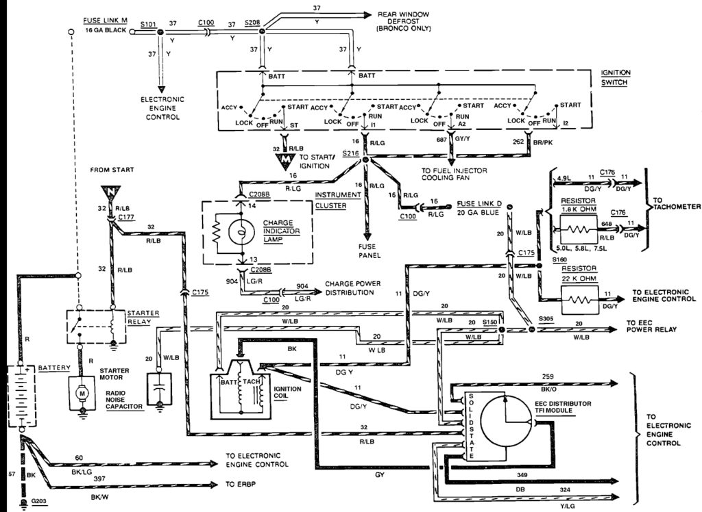
An ignition switch contains three separate switches that feed the battery’s current to different locations. The first switch is used to power the choke by pushing it, while the third switch is used to control the ON/OFF setting. Different manufacturers have different colors-coding systems to match the conductors. OMC uses the same method. Connectors can be attached to the ignition switch in order to include the digital Tachometer.
While some ignition switch terminals do not come in original form however, the numbers may not match that of the diagram. Before plugging into the ignition switch, make sure to check the continuity. A multimeter that is inexpensive can aid in this. After you’re satisfied with the continuity of the wires it is time to install the new connector. If you have an ignition switch supplied by the manufacturer the wiring loom may be distinct from the one that is you have in your car.
It is essential to know the way that ACC outputs and the auxiliary outputs function to connect them. The ACC and IGN terminals are the default connections for your ignition switch, and the START and IGN terminals are the principal connections for the stereo and radio. The ignition switch is responsible to turn the engine of your car on and off. On older cars, the ignition switch terminals are marked with the letters “ACC” as well as “ST” (for the individual magnetic wires).
Terminals for coil
Understanding the terminology is the first step to finding out what kind of ignition coil you’ve got. There are a variety of connections and terminals within an ignition wiring schematic that include two primary as well as two secondary. The coils have a specific operating voltage. The initial method of determining what type you’ve got is to check the voltage on S1, the primary terminal. S1 must also be inspected for resistance in order to identify whether it’s a Type B, B, or an A coil.
The chassis’ negative needs to be connected to the side of low-tension. This is the ground on the ignition wiring diagram. The high-tension side delivers positively direct to the spark plugs. It is necessary for the purpose of suppression that the body of the coil’s metal be connected to its chassis, however, it is not necessary. The diagram of the ignition wiring will also indicate the connection of the positive coil’s terminals. In certain cases it is recommended to conduct a scan at your local auto parts store can help you identify malfunctioning ignition coils.
The black-and-white-striped wire from the harness goes to the negative terminal. The positive terminal is connected to the white wire and an trace of black. The black wire connects to the contact breaker. You can check the connections with a paperclip to remove the wires from the housing. Make sure that the terminals aren’t bent.
Accessory Terminals
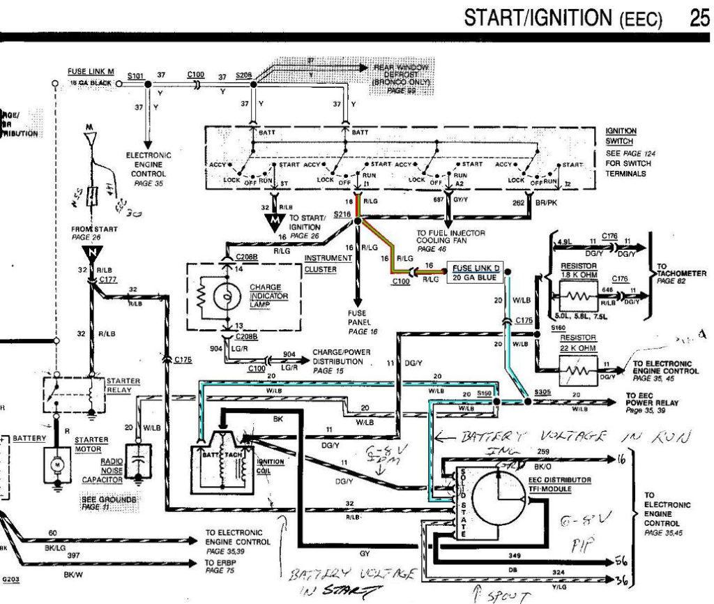
Ignition wiring diagrams show the various wires used to power the car’s various parts. There are generally four terminals with color codes that are connected to the component. Red refers to accessories, yellow the battery, and green the starter solenoid. The “IGN” terminal can be utilized to turn on the car, turn on the wipers, and other functions. The diagram below illustrates how to connect the ACC terminal and ST terminals to other components.
The battery is attached to the terminal named BAT. The electrical system won’t start without the battery. A dead battery can make the switch stop turning on. You may refer to the wiring diagram if you’re uncertain about where the car’s batteries are. The ignition switch as well as the battery are connected by the accessory terminals. The BAT Terminal is connected to the Battery.
Certain ignition switches have an additional position. This lets users connect their outputs to another location without the ignition. Customers sometimes want the output of the auxiliary to be operated independently of the ignition. To make use of the auxiliary output, connect the connector with the same colors as the ignition, and connect it to the ACC terminal on the switch. This option is useful however it does have one major distinction. Most ignition switches will be in an ACC position if the car is in ACC however, they’ll be at the START position if the vehicle is in IGN.
Gallery of 1988 F150 Ignition Wiring Diagram
Gallery of 1988 F150 Ignition Wiring Diagram


