1988 Ford F250 Ignition Switch Wiring Diagram – Let’s begin by looking at different types terminals found on an ignition switch. These terminals include the Ignition switch, the Coil along with the Accessory. After we’ve identified what these terminals are then we can determine the various components in the ignition wiring. We will also discuss what functions are available for the Ignition switch, as well as the Coil. Then, we will concentrate on the accessories terminals.
The terminals are for ignition switches.
An ignition switch is comprised of three switches. They feed the voltage of the battery to many different locations. The choke is powered by the first switch. The second switch is responsible for the ON/OFF of the ignition switch. Different manufacturers have their own color-coding system for the various conductors, which is explained in a different article. OMC employs this system. A tachometer adapter is installed on the ignition switch that allows for the addition of the tachometer.
While most ignition switch terminals can be duplicated, the numbers may not be consistent with the diagram. Examine the continuity of the wires first to ensure they’re connected correctly to the ignition switch. This can be accomplished with a multimeter that is inexpensive. Once you’re satisfied about the continuity of your wires, you will be able to install the new connector. The wiring loom of an ignition switch that’s supplied by the manufacturer will differ from the one that you have in your car.
Before connecting the ACC outputs to your car’s auxiliary outputs It is essential to understand the basics of these connections. The ACC and IGN connectors are the standard connections of the ignition switch. Although the START, IGN, and ACC terminals are the main connections for the radio or stereo, the START/IGN terminals are the main ones. The ignition switch is responsible to turn the car’s engines on and off. Older vehicles have ignition switch terminals labeled “ACC” or “ST” (for individual magnetowires).
Terminals for coil
The language used to decide the model and type of an ignition coil is the most important thing. The diagram of the basic ignition wiring shows a number different connections and terminals. There are two primary and one secondary. Each coil has an operating voltage. The first step in determining which kind of coil you’re using is to examine the voltage of S1 or the primary terminal. S1 must also be subjected to resistance tests to determine if it is a Type A or B coil.
The chassis’ negative must be connected to the side of low-tension. This is also the ground on the diagram of the ignition wiring. The high-tension side supplies positive direct to the spark plugs. It is necessary for suppression purposes that the coil’s metallic body be connected to its chassis but not essential. The ignition wiring diagram will also indicate the connection of the positive coil terminals. Sometimes, an inspection at an auto parts shop can identify a problem with the ignition wire.
The black-and-white-striped wire from the harness goes to the negative terminal. The positive terminal is connected to the white wire, which has the trace of black. The black wire is connected to the contact breaker. It is possible to remove the black wire from the plug housing with a paper clip if you are unsure about the connection. It’s also essential to make sure the terminals do not bend.
Accessory terminals
Diagrams of the ignition wiring illustrate the wiring used to power various parts of the vehicle. There are typically four colored terminals that correspond to each component. The accessories are red and the battery yellow and the starter solenoid is green. The “IGN” terminal is used to turn on the car and operate the wipers and other operating functions. The diagram shows how you can connect the ACC and ST terminals to the other components.
The terminal BAT is the connection for the battery. The electrical system will not start when the battery isn’t connected. In addition the switch isn’t turned on. It is possible to view the wiring diagram of your car to see the location of your car’s batteries. placed. The ignition switch is connected to the car’s battery. The BAT Terminal is connected to the Battery.
Some ignition switches include an accessory setting where users can adjust their outputs and manage them without having to turn on the ignition. Some customers want the output of the auxiliary to be used independently from the ignition. You can use the additional input by connecting it to the ACC terminal. This is a great feature, but there is an important distinction. Most ignition switches will have an ACC position when the vehicle is in ACC however they will be in the START position if the vehicle is IGN.
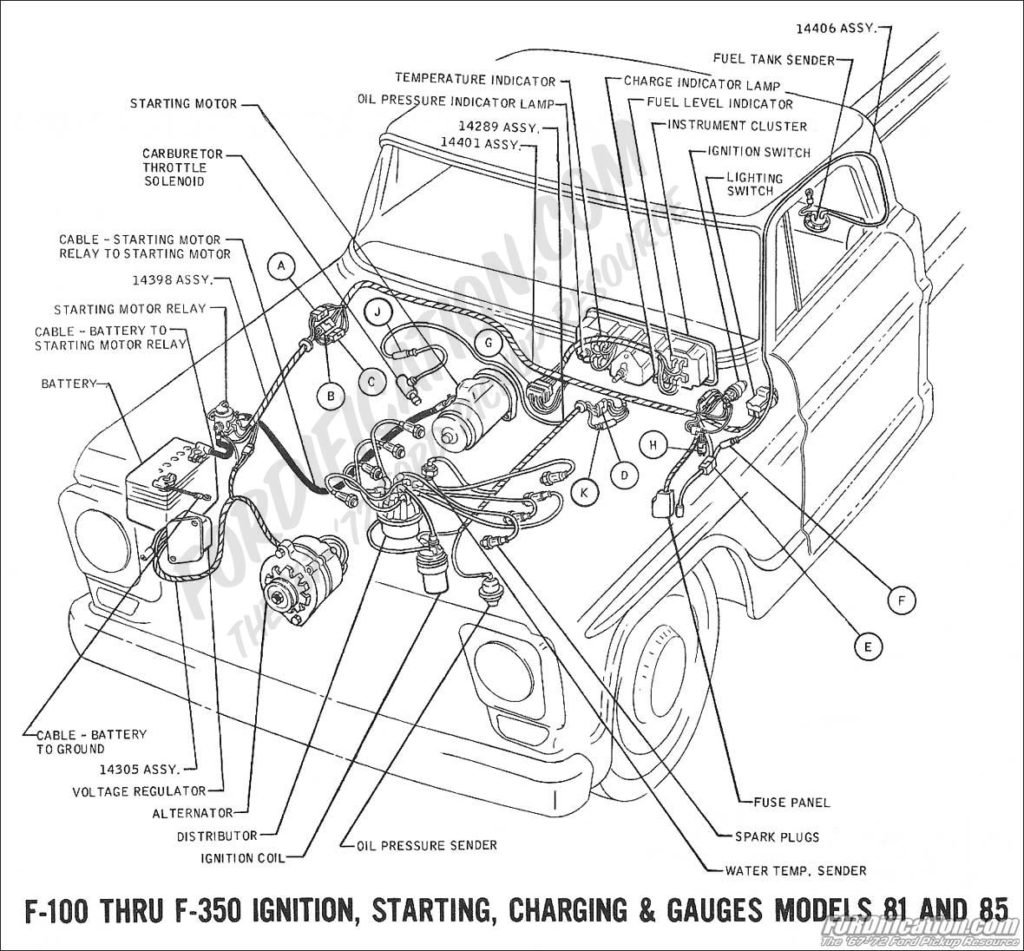
Gallery of 1988 Ford F250 Ignition Switch Wiring Diagram
Gallery of 1988 Ford F250 Ignition Switch Wiring Diagram


