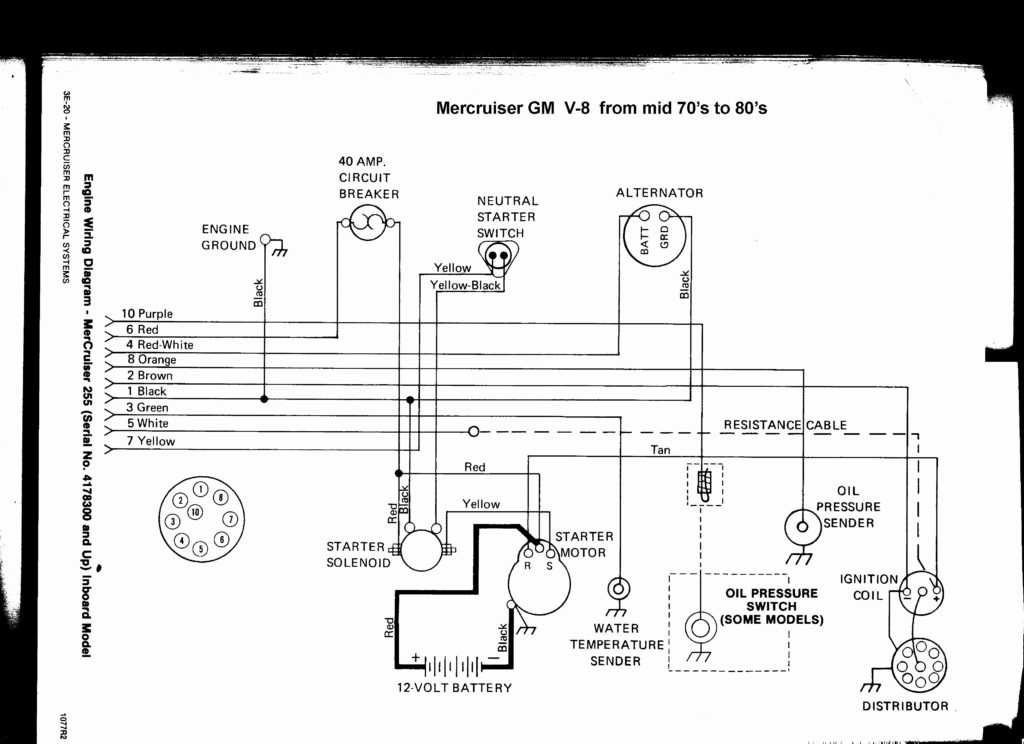
1988 Mercruiser 5.7 Ignition Wiring Diagram – Let’s first look at the different terminals on the ignition switch. These terminals comprise the Ignition switch as well as the Coil as well as the Accessory. When we have a clear understanding of the purpose of each type of terminal, we can then identify the parts of the ignition wiring. In addition, we will discuss the function of the Ignition switch and Coil. The next step is to focus on the accessory terminals.
Ignition switch terminals
There are three separate switches on an ignition switch that provide the battery’s voltage to various destinations. The ON/OFF position of the ignition switch is controlled by the third switch, which supplies power to the choke whenever it is pushed. Different manufacturers use different color-coding methods to identify different conductors. We’ll discuss this in a separate article. OMC uses this method. A connector can be added to the ignition switch in order to connect the digital Tachometer.
Although the majority of ignition switch terminals can be duplicated, the number may not be in line with the diagram. Before plugging in the ignition switch, be sure to test the continuity. A multimeter is a great tool to check the continuity. After you’re happy with the continuity of your wires, you’ll be able to install the new connector. The wiring loom in the ignition system switch supplied by the manufacturer is different.
First, understand the differences between ACC and the auxiliary outputs. The ACC and IGN terminals are the default connections on your ignition switch. the START and IGN terminals are the principal connections to the radio and stereo. The ignition switch turns the car’s engine ON and off. The terminals of older cars ignition switches are marked by “ACC” as well as ST (for the individual magneto wires).
Terminals for coil
The first step in determining the type of ignition coil is to know the terms used. An understanding of the basic wiring diagram for ignition will reveal a variety of connections and terminals. It is essential to identify the type of coil you have by testing the voltage at the primary terminal, called S1. S1 should be checked for resistance to determine if the coil is Type A, B, and/or C.
The coil’s low-tension component is to be connected to the chassis positive. This is the ground of the wiring for ignition. The high-tension side supplies positive directly to the spark plugs. For suppression purposes, the coil’s body metal must be connected with the chassis. It’s not necessary to use electricity. A wiring diagram can depict the connection between positive and negative coils. Sometimes, an inspection at an auto parts store could diagnose a malfunctioning ignition wire.
The black-and-white-striped wire from the harness goes to the negative terminal. The positive terminal receives the other white wire with a trace of black. The black wire connects to the contact breaker. To verify the connections, use a paperclip or a pencil to lift them out of the plug housing. Make sure you verify that the connections haven’t been bent.
Accessory terminals
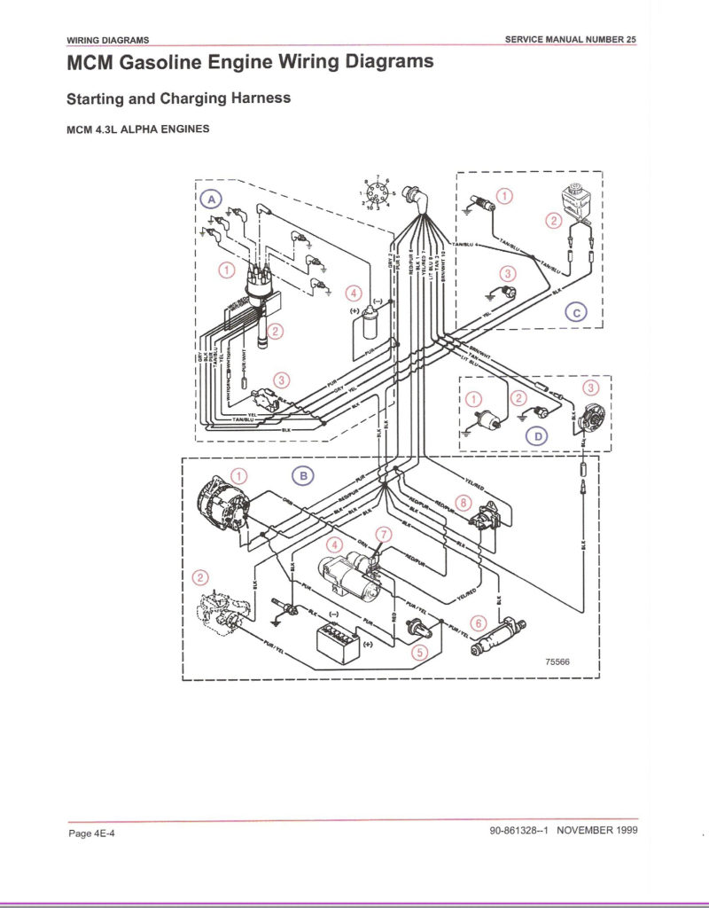
Diagrams of ignition wiring show the wires that are used to power the vehicle’s electrical supply. There are generally four color-coded terminals to each component. The accessories are colored red, the battery is yellow the starter solenoid green. The “IGN terminal” is used to power the wipers and other operating features. The diagram illustrates how you can connect ACC or ST terminals, and other.
The terminal BAT connects the battery to the charger. The electrical system can’t start without the battery. A dead battery could cause the switch to not turn on. To find the battery in your car, check your wiring diagram. The accessory terminals on your car are connected to the battery and the ignition switch. The BAT Terminal is connected to the Battery.
Some ignition switches offer the option of an “accessory position” that allows users to adjust their outputs independently of the ignition. Sometimes, customers wish to use the auxiliary output separate from the ignition. In order to use the auxiliary output, connect the connector using the same colors as the ignition and connect it to the ACC terminal on the switch. This is a convenient feature however it does have one significant differentiator. The majority of ignition switches are set to operate in the ACC position when the car is in the ACC position, whereas they’re set to the START position when the car is in the IGN position.
Gallery of 1988 Mercruiser 5.7 Ignition Wiring Diagram
Gallery of 1988 Mercruiser 5.7 Ignition Wiring Diagram


