1990 Honda Civic Ignition Wiring Diagram – We will first examine the various types of terminals found on the ignition switch. These terminals are used for the Ignition button, Coil and Accessory. After we’ve identified the purpose of the terminals we can identify the various parts of the ignition wiring. Then, we will discuss the functions as well as the Coil. The next step is to focus on the accessory terminals.
Ignition switch terminals
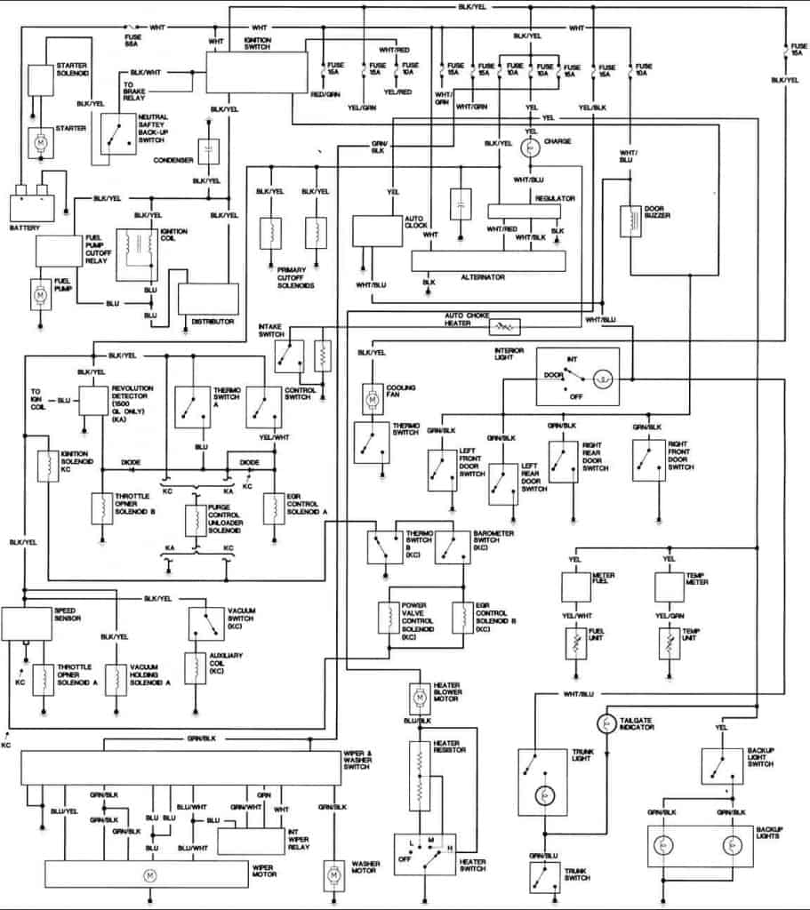
Three switches are located in an ignition switch. Each of these switches feeds the battery’s voltage to various places. The first switch supplies power to the choke whenever pushed, and the second is the position of the ignition switch’s ON/OFF. Different manufacturers have different colour-coding systems that correspond to the conductors. OMC employs this system. The ignition switch also includes an adapter for the addition of the Tachometer.
Even though some of the ignition switch terminals could not be authentic, the numbering of each may not be in line with the diagram. Check the continuity of all the wires to make sure they’re properly connected to the ignition switches. A multimeter is a great instrument to verify the continuity. After you’re sure that the wires are in good order and you are able to connect the new connector. If your vehicle has an ignition switch that is installed the wiring diagram may differ.
For connecting the ACC outputs to the auxiliary outputs on your car, you need to understand how these two connections work. The ACC and IGN terminals are the default connections for the ignition switch. the START and IGN terminals are the principal connections for stereo and radio. The ignition switch is responsible for turning the car’s engine on and off. Older vehicles have ignition switch’s terminals that are labeled “ACC” or “ST” (for individual magnetowires).
Terminals for coil
To identify the kind of ignition coil you need to know the step is to understand the terminology. A basic diagram of the wiring will provide you with a range of connections and terminals. Each coil is operating at a certain voltage. The first step to determine the kind you have is to check the voltage on S1, or the primary terminal. S1 should also be checked for resistance to determine if the coil is a Type B, B, or A coil.
The chassis’ negative needs to be connected to the low-tension side. This is what you find in the wiring diagram. The high-tension part provides positive direct to the sparkplugs. To prevent noise the coil’s metal body is required to be connected to the chassis. It’s not necessary to use electricity. The diagram of the ignition wiring will also demonstrate how to connect the positive and negative coil’s terminals. You may find an issue with your ignition coil that is easily identified by looking it up at the auto parts shop.
The black-and-white-striped wire from the harness goes to the negative terminal. The positive terminal also gets the second white wire, which has a black trace. The contact breaker is attached to the black wire. You can remove the black wire from the housing of the plug by using a paperclip in case you are uncertain about the connection. Be sure the terminals do not bend.
Accessory terminals
Diagrams of ignition wiring depict the wires that provide power to various components of the car. There are usually four terminals with color codes that are connected to each component. Red is used for accessories, yellow is for the battery, and green is for the starter solenoid. The “IGN” terminal is used to turn on the car, turn on the wipers and other features. The diagram shows the connections between the ACCand ST terminals.
The terminal known as BAT is where the battery is connected. The electrical system won’t start without the battery. A dead battery can cause the switch to not come on. You may refer to the wiring diagram if you’re not sure where the batteries of your car are located. The ignition switch and battery are connected by the accessory terminals. The BAT terminal is connected to the battery.
Certain ignition switches have an additional position. This allows users to connect their outputs to a different place without the ignition. Some customers might want to utilize the auxiliary input separately from the ignition. In order to use the auxiliary output, connect the connector with the same colors as the ignition, connecting it to the ACC terminal on the switch. This is a useful option, but there’s one important difference. The majority of ignition switches have an ACC position if the car is in ACC, but they’ll be at the START position when the car is in IGN.
Gallery of 1990 Honda Civic Ignition Wiring Diagram
Gallery of 1990 Honda Civic Ignition Wiring Diagram


