1996 Ford F150 Ignition Wiring Diagram – Let’s first take a look at the different types of terminals that are used in the ignition switch. They are terminals for Coil, Ignition Switch, and Accessory. Once we know what these kinds of terminals are, we will proceed to discover the various components of the 1996 Ford F150 Ignition Wiring Diagram. We’ll also be discussing the roles of the Ignition switch and Coil. Then, we’ll talk about the roles of the Ignition switch as well as Coil.
Terminals for ignition switch
Three switches can be found on the ignition switch. Each of the three switches feeds the battery’s voltage to several different destinations. The first switch supplies power to the choke, while the second toggles the status of the ignition switch. Different manufacturers have different color-coding systems to identify different conductors. This will be covered in a different article. OMC uses this method. The connector permits the connection of a speedometer to the ignition switch.
Even though some ignition switch terminals don’t appear in their original configuration The numbering might not match the diagram. The first step is to check the continuity of all the wires to ensure that they are properly connected to the ignition switches. You can check this using an inexpensive multimeter. Once you are satisfied that the wires are in good order and you are able to connect the new connector. If you’re using an ignition switch supplied by the manufacturer the wiring loom will be distinct from the one that is in your car.
In order to connect the ACC outputs to the auxiliary outputs of your car, you need to understand the way these two connections function. The ACC terminals as well as the IGN terminals are the standard connections for your ignition switch. The START and IGN connections are the most important connections for radio and stereo. The ignition switch is the one that controls the engine of your car. Older cars have the ignition switch terminals labeled “ACC” or “ST” (for individual magnetowires).
Terminals for coil
Understanding the terms is the first step towards finding out what kind of ignition coil you own. You will see several connections and terminals on the basic wiring diagram for ignition which includes two primary and two secondary. Each coil has a specific operating voltage. To determine the type of coil you own first, you need to determine the voltage at the S1 primary terminal. S1 must also be inspected for resistance to determine whether it’s a Type B, B, or an A coil.
The negative end of the chassis end should be connected to connect to the coil’s lower-tension end. It is also the ground in the diagram of ignition wiring. The high-tension side supplies the positive power direct to the spark plugs. The coil’s metal body needs to be connected to the chassis to suppress the effect, but it is not electrically required. The wiring diagram of the ignition will explain how to connect the two terminals of the positive and negative coils. In some instances you’ll discover that an ignition coil that is malfunctioning is identified by scans at an auto parts store.
The black-and-white-striped wire from the harness goes to the negative terminal. The terminal for the negative is served by the black trace that’s joined to the white wire. The contact breaker is connected to the black wire. To check the connections between the two wires use a paperclip and remove them out of the housing. You should also check to see that the terminals are not bent.
Accessory Terminals
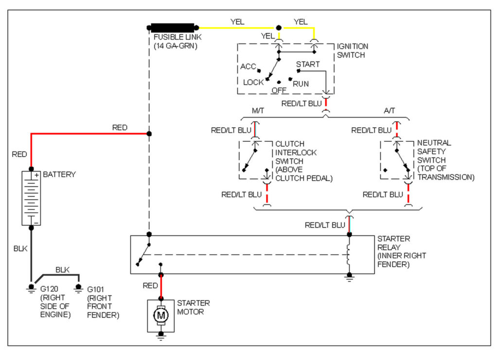
The ignition wiring diagrams illustrate the various wires used to power the car’s various parts. Each part has four distinct color-coded connections. To identify accessories, red stands the starter solenoid’s color, blue for battery, and blue is for accessory. The “IGN terminal” is used to provide power to the wipers along with other operational features. This diagram shows how you can connect ACC and ST terminals to the other components.
The terminal BAT connects the battery to the charger. The electrical system won’t start without the battery. In addition, the switch will not start. To find your car’s battery examine the wiring diagram. The accessory terminals of your car connect to the battery as well as the ignition switch. The BAT terminal is connected to the battery.
Some ignition switches are equipped with an accessory position. This allows users to access their outputs from a different place without having to turn on the ignition. Sometimes, customers would like an auxiliary output that can be used independently from the ignition. The auxiliary output is utilized by wiring the connector with the same colors as your ignition, and then attaching it to the ACC terminal of the switch. This is a useful option, but there’s an important difference. Most ignition switches come with the ACC position when your car is in ACC mode and a START position when you are in IGN.
Gallery of 1996 Ford F150 Ignition Wiring Diagram
Gallery of 1996 Ford F150 Ignition Wiring Diagram


