1998 Honda Civic Ignition Wiring Diagram – Let’s first examine the various terminals on the ignition switch. The terminals are the Ignition switch and Coil along with the Accessory. Once we have identified what these terminals do, we will identify the different parts in the ignition wiring. We’ll also discuss the functions as well as the Coil. Then, we’ll talk about the roles of the Ignition switch and Coil.
Terminals of ignition switch
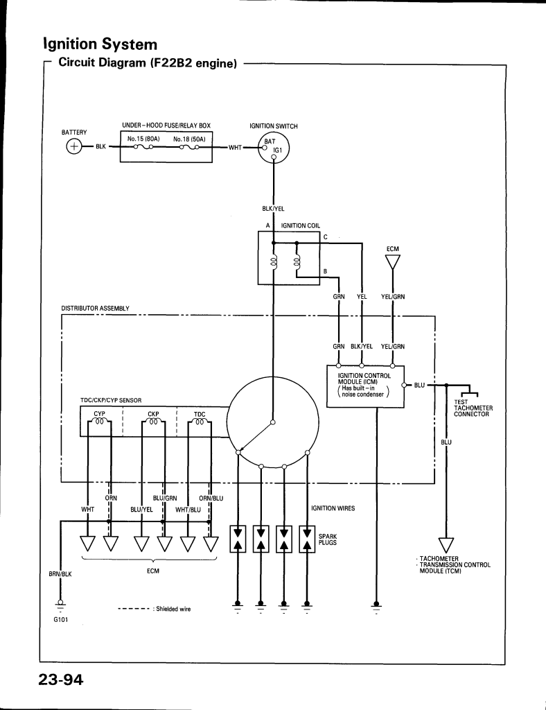
An ignition switch is comprised of three switches. They feed the voltage of the battery to many different locations. The choke is powered by the first switch. The second switch is responsible for the ON/OFF switch of the ignition switch. Different manufacturers use different colors-coding systems to match the conductors. OMC utilizes this system. There is a connector in the ignition switch to allow attaching an Tachometer.
While many ignition switch terminals may not be original, the numbers of the terminals may not be in line with the diagram. The first step is to check the continuity of all the wires to make sure they’re properly connected to the ignition switches. A multimeter that is inexpensive can aid in this. After you’re happy with the continuity of the wires, you can install the new connector. If your vehicle is equipped with an ignition switch that is installed the wiring diagram will differ.
Knowing how the ACC outputs connect to the other outputs inside your car is vital. The ACC, IGN and START terminals are the primary connection to the ignition switch. They also function as the primary connections to your radio and stereo. The ignition switch is the engine’s on/off button. Older cars are identified by the letters “ACC”, “ST”, (for individual magneto cables) on their ignition switch terminals.
Terminals for coil
Understanding the terminology is the initial step in finding out what kind of ignition coil you own. You’ll see a number of connections and terminals within a basic ignition wiring schematic, including two primary, as well as two secondary. The voltage that operates on each coil is different. This is why it is crucial to test the voltage at S1 (primary terminal). S1 should be checked for resistance to determine if the coil belongs to Type A, B, and/or C.
The negative end of the chassis must be connected to connect the coil’s low-tension side. This is the ground of the wiring for ignition. The high-tension component supplies the spark plugs with positive. To prevent noise, the coil’s body metal must be connected to the chassis. This is not necessary to use electricity. There are also connections of the positive and the negative coil terminals on the diagram of the ignition wiring. In certain instances it is recommended to conduct a scan at your local auto parts store can help you identify the malfunctioning ignition coils.
The black-and-white-striped wire from the harness goes to the negative terminal. The other white wire is black-colored and goes to the terminal opposite. The black wire connects to the contact breaker. To check the wires’ connections, employ a paperclip to lift them from the housing. Be sure to check that the terminals haven’t been bent.
Accessory terminals
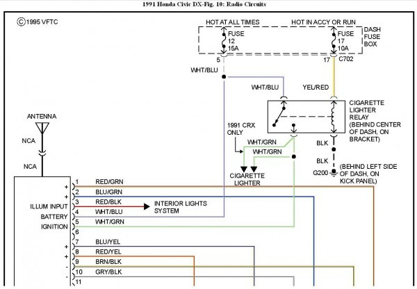
Ignition wiring diagrams show the different wires that are utilized to power the vehicle’s various components. There are generally four color-coded terminus for each component. The accessories are colored red while the battery is yellow and the starter solenoid green. The “IGN” terminal is used to start the car, operating the wipers, and for other functions. The diagram shows how you can connect the ACC and ST terminals to the rest of the components.
The battery is attached to the terminal whose name is BAT. The electrical system can’t start without the battery. The switch will not turn on if the battery isn’t present. It is possible to view your wiring diagram to figure out the location of your car’s batteries. placed. The accessory terminals in your car are connected to the battery and the ignition button. The BAT terminal is connected to the battery.
Some ignition switches come with an additional “accessory” position, in which users can control their outputs with no ignition. Sometimes, customers wish to use the auxiliary output separately from the ignition. The auxiliary output could be utilized to connect the connector with the same color as your ignition, and then connecting it to the ACC terminal of the switch. This is a useful feature, but there is one important distinction. Some ignition switches are programmed to have an ACC position once the car is in the ACC position. They will also be in the START mode after the vehicle has been entered the IGN position.
Gallery of 1998 Honda Civic Ignition Wiring Diagram
Gallery of 1998 Honda Civic Ignition Wiring Diagram


