1999 Honda Civic Ignition Switch Wiring Diagram – Let’s first examine the various terminals on the ignition switch. These terminals are for the Ignition button, Coil and Accessory. Once we know the purpose of these terminals and what they do, we can then identify the different parts in the ignition wiring. We will also talk about the functions and the Coil. We will then discuss the function of the Ignition switch and Coil.
Terminals for ignition switch
An ignition switch has three separate switches that feed the battery’s current to various destinations. The first is utilized to turn on the choke by pushing it, and the third switch is used to control the ON/OFF position. Different manufacturers employ different colors for different conductors. This is discussed in another article. OMC follows this scheme. A tachometer adapter is installed on the ignition switch, allowing for the addition of an Tachometer.
While the majority of ignition switch terminals do not appear in their original configuration The numbering might not match that of the diagram. Before you plug into the ignition switch, ensure that you check the continuity. This can be accomplished with a simple multimeter. When you are happy with the continuity of the wires install the new connector. The wiring loom of an ignition switch that’s supplied by the factory will be different from the one in your car.
Before connecting the ACC outputs to your car’s auxiliary outputs It is essential to understand the basics of these connections. The ACC/IGN connections function as the default connections on the ignition switch. The START/IGN terminals connect to the radio or stereo. The ignition switch is the one that controls the engine of your car. The terminals of the ignition switch on older cars are labeled with the alphabets “ACC” and “ST” (for each magneto wires).
Terminals for coil
The first step in determining the kind of ignition coil is to know the terms employed. In a basic ignition wiring diagram there are a number of different connections and terminals, which include two primary and two secondary. It is essential to identify the type of coil that you are using by testing the voltage at the primary terminal, called S1. S1 should be checked for resistance to determine if the coil is Type A, B, and/or C.
The coil’s low-tension side should be connected at the chassis’s minus. This is the ground of the wiring for ignition. The high-tension end supplies positive direct to the sparkplugs. To prevent noise the coil’s body metal is required to be connected to the chassis. It’s not necessary for electrical use. The wiring diagram of the ignition will show you how to connect the two terminals of the positive or negative coils. Sometimes, an inspection at an auto parts shop can diagnose a malfunctioning ignition wire.
The black-and-white-striped wire from the harness goes to the negative terminal. The terminal for the negative is served by the black trace that’s connected to the white wire. The black wire connects with the contact breaker. To check the connections, you can make use of a paperclip or pencil to lift them out of the plug housing. It’s also crucial to make sure that the terminals aren’t bent.
Accessory terminals
Diagrams of the ignition wiring show the wires used to power various parts of the car. Each component has four distinct color-coded connections. The red color is for accessories, yellow the battery, and green the starter solenoid. The “IGN” terminal can be used to start the car and operate the wipers, as well as other operating functions. The below diagram shows how to connect the ACC terminal and ST terminals to the other components.
The terminal BAT is the connection to the battery. The electrical system can’t start without the battery. Additionally, the switch doesn’t turn on. A wiring diagram can inform the location of the battery of your car. The accessory terminals on your car are connected to the battery as well as the ignition switch. The BAT terminal is connected with the battery.
Some ignition switches feature an “accessory” position that permits users to regulate their outputs without needing to turn on the ignition. Sometimes, customers want to make use of an additional output that is independent of the ignition. Use the secondary output by connecting the connector to the ACC terminal on the switch using the same colors. This convenience feature is great however, there’s one differentiator. Most ignition switches are configured to operate in the ACC position when the car is in the ACC position, whereas they’re set to the START position when the vehicle is in the IGN position.
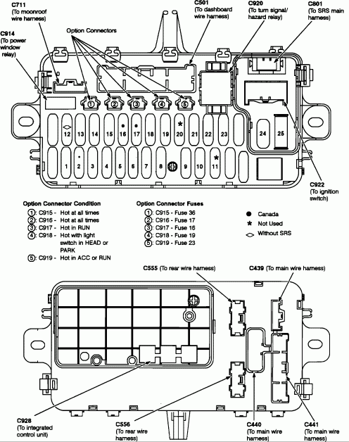
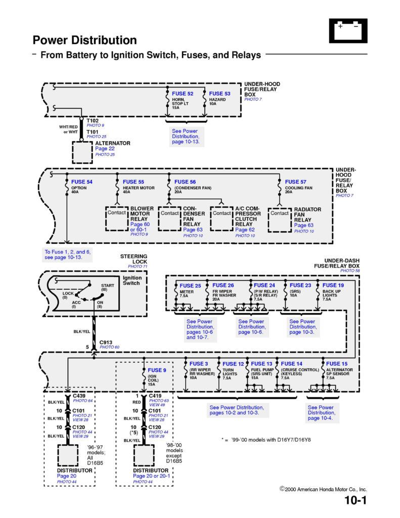
Gallery of 1999 Honda Civic Ignition Switch Wiring Diagram
Gallery of 1999 Honda Civic Ignition Switch Wiring Diagram


