2000 Honda Accord Ignition Switch Wiring Diagram – In the beginning, we’ll look at the different types of terminals that are found in the ignition switch. The terminals are the Ignition switch and Coil and the Accessory. Once we understand the function of each type of terminal, it is possible to identify the various components of the ignition wiring. We’ll also discuss the functions of the Ignition switch, and Coil. We will then concentrate on the accessory terminals.
Terminals for the ignition switch
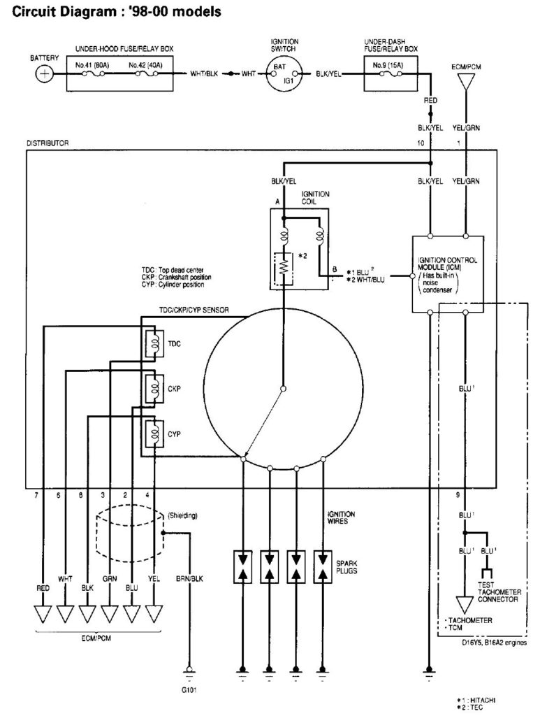
The ignition switch consists of three switches. They are the ones that supply the battery’s power to several locations. The first switch powers the choke. The second switch is responsible for the ON/OFF of the ignition switch. Every manufacturer has its own color-coding system, which we will discuss in another article. OMC follows this system. The connector allows for the attachment of a speedometer to the ignition switch.
Although some ignition switch terminals might not be original, the numbers of the terminals may not match the diagram. Examine the electrical continuity first to ensure they’re properly connected to the ignition switch. This can be checked using a cheap multimeter. Once you’ve verified the continuity of the wires you are able to connect the connector. The wiring loom of the ignition switch factory-supplied will be different than the one in your car.
In order to connect the ACC outputs to the auxiliary outputs on your car, you’ll need first know how these two connections work. The ACC/IGN connections function as the default connection on the ignition switch. The START/IGN connections connect to the radio or stereo. The ignition switch switches the engine of your car ON and off. The terminals of older cars’ ignition switches are labeled by “ACC” as well as ST (for individual magneto wires).
Terminals for coil
To figure out the type of ignition coil, the first step is to know the terminology. There are a variety of connections and terminals in a basic ignition wiring schematic that include two primary and two secondary. You must determine the kind of coil you are using by testing the voltage on the primary terminal, called S1. S1 should also be tested for resistance in order to identify if the coil is an A, Type B or an A coil.
The low-tension coil side must be connected at the chassis’ less. This is the wiring diagram you will find in the diagram of wiring. The high-tension supply provides positively directly to spark plugs. It is essential to suppress the coil’s metallic body be connected to its chassis, but not essential. The diagram of the ignition wiring will also indicate the connections of the positive coil’s terminals. You may find an issue with the ignition coil that can be easily diagnosed by scanning it in an auto parts retailer.
The black-and-white-striped wire from the harness goes to the negative terminal. The white wire is black-colored and goes to the negative terminal. The black wire connects to the contact breaker. It is possible to remove the black wire from the housing of the plug using a paper clip in case you are uncertain about the connections. Make sure you check that the terminals haven’t been bent.
Accessory terminals
The diagrams for ignition wiring show the wires used to power the vehicle’s electrical supply. There are typically four color-coded terminals that correspond to each component. To identify accessories, red stands the starter solenoid’s color, blue for battery, and blue is for accessories. The “IGN” terminal can be used to start the vehicle and control the wipers as well as other operational features. The diagram shows the connections of the ACCas well as ST terminals.
The terminal known as BAT is where the battery is connected. Without the battery the electrical system can not get started. Furthermore, the switch doesn’t turn on. You can view your wiring diagram to figure out where the batteries of your car are located. The ignition switch is connected to the battery of your car. The BAT connector is connected to your battery.
Some ignition switches offer an additional “accessory position” that allows users to alter their outputs without the ignition. Some customers prefer to use an auxiliary output independent of the ignition. You can use the auxiliary output by connecting it to the ACC terminal on your switch that has the same color. This convenience feature is great, but there is one difference. Most ignition switches come with the ACC position when your car is in the ACC mode, and a START position when the switch is in IGN.
Gallery of 2000 Honda Accord Ignition Switch Wiring Diagram
Gallery of 2000 Honda Accord Ignition Switch Wiring Diagram


