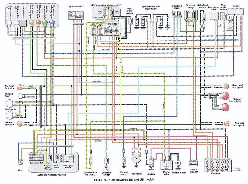
2005 Gsxr 1000 Ignition Wiring Diagram – We will first look at the various types of terminals that are used on the ignition switch. These are the terminals that connect the Ignition, Coil, or Accessory. After we’ve established what these kinds of terminals are We will then identify the different parts of the 2005 Gsxr 1000 Ignition Wiring Diagram. In addition, we will discuss the function of the Ignition switch and Coil. Then, we’ll talk about the roles of the Ignition switch as well as Coil.
Terminals of ignition switch
An ignition switch has three switches. They feed the voltage of the battery to different places. The first is used to turn on the choke through pushing it. Then, another switch controls the ON/OFF setting. Different manufacturers employ different color codes for various conductors. This is explained in a different article. OMC utilizes this method. An additional connector is included in the ignition switch for attaching a to a tachometer.
Even though some of the ignition switch terminals might not be original, the numbers of the terminals may not be in line with the diagram. It is important to first verify the continuity of the wires to ensure that they are connected to the ignition switch correctly. A cheap multimeter can assist you in this. Once you are satisfied that the wires are running in good harmony and you are able to connect the new connector. If your car has an ignition switch that is installed the wiring diagram will differ.
You must first understand how the ACC outputs and auxiliary outputs work in order to connect them. The ACC and IGN connectors are the default connections of your ignition switch. While the START, IGN, and ACC terminals are the main connections for the radio or stereo, the START/IGN terminals are the most important ones. The ignition switch is accountable to turn the car’s engines on and off. The terminals of older cars ignition switches are identified by “ACC” and ST (for specific magneto wires).
Terminals for coil
Understanding the terminology is the initial step towards knowing what type of ignition coil you’ve got. The diagram of the basic ignition wiring shows a number different connections and terminals. There are two primary and one secondary. You must determine the type of coil that you have by testing the voltage at the primary terminal, S1. S1 must also be subjected to resistance tests to determine if it are an A or B coil.
The coil’s low-tension side should be connected to the chassis’ less. This is what you see in the diagram of wiring. The high-tension side provides the spark plugs with positive. To prevent noise, the coil’s metal body is required to be connected to the chassis. It is not necessary to connect the coil electrically. A wiring diagram can also depict the connection between positive and negative coil terminals. You may find an issue with your ignition coil that is easily identified by scanning it in an auto parts store.
The black-and-white-striped wire from the harness goes to the negative terminal. The white wire is black-colored and goes to the terminal opposite. The black wire connects to the contact breaker. To confirm the connections, you can make use of a paperclip or pencil to lift them out from the plug housing. It is also important to make sure the terminals do not bend.
Accessory Terminals
Diagrams of the ignition wiring illustrate the wiring used to power various parts of the vehicle. There are generally four colors of terminals connected to each part. The accessories are colored red while the battery is yellow, and the starter solenoid is green. The “IGN terminal is used to start the car, operating the wipers and other functions. The diagram below shows how to connect the ACC terminal as well as the ST terminals to various components.
The terminal BAT connects the battery to the charger. The electrical system can’t begin without the battery. Also, the switch won’t start without the battery. The wiring diagram will show you the location of the battery of your car. The ignition switch is linked to the car’s battery. The BAT connector is connected to the battery.
Some ignition switches come with an additional “accessory position” which allows users to modify their outputs independent of the ignition. Sometimes, customers want to utilize an additional output that is independent of the ignition. It is possible to use the additional input by connecting it to the ACC terminal. While this is an excellent option, there’s a thing you need to know. Most ignition switches are set up to have an ACC status when the vehicle is in the ACC or START position.
Gallery of 2005 Gsxr 1000 Ignition Wiring Diagram
Gallery of 2005 Gsxr 1000 Ignition Wiring Diagram


