2008 Chevy Malibu Ignition Wiring Diagram – We’ll begin by looking at the different types of terminals in an ignition switch. These terminals serve for the Ignition button, Coil and Accessory. When we have a clear understanding of the purpose of each type of terminal, we are able to determine the components of the ignition wiring. We’ll also discuss the functions of the Ignition switch, as well as the Coil. After that, we’ll turn our attention to the Accessory terminals.
The terminals are for ignition switches.
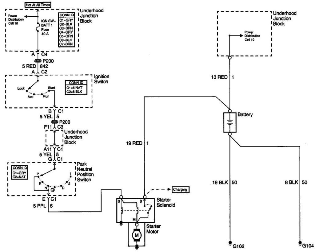
Three switches are found on an ignition switch. Each of these switches feeds the battery’s voltage to several different destinations. The first switch is utilized to drive the choke by pushing it, while another switch controls the ON/OFF position. Different manufacturers use different colors-coding systems to match the conductors. OMC utilizes the same system. The ignition switch also includes a connector for adding an Tachometer.
Although the majority of ignition switch terminals don’t carry an original number, they might have a different one. Check the integrity of the wires first to ensure they’re connected correctly to the ignition switch. A cheap multimeter can assist you in this. When you’re satisfied that all wires are in good order, you can attach the new connector. The wiring loom of an ignition switch that’s factory-supplied will be different than the one in your vehicle.
Understanding how ACC outputs are connected to the other outputs of your car is essential. The ACC, IGN and START terminals are the default connection to the ignition switch. They also function as the main connections to the radio and stereo. The ignition switch acts as the engine’s off/on button. Older cars are equipped with ignition switch’s terminals that are labeled “ACC” or “ST” (for individual magnetowires).
Coil terminals
Understanding the terms is the first step to finding out what kind of ignition coil you have. In a typical diagram of the wiring for ignition there are several different connections and terminals, which include two primary and two secondary. Each coil has an operating voltage. The first step in determining which kind of coil you’re dealing with is to test the voltage on S1, or the primary terminal. S1 must also be subjected to resistance tests to determine if it is an A or B coil.
The negative end of the chassis should be connected to to the coil’s lower-tension end. This is what’s called the ground in the ignition wiring diagram. The high-tension side delivers the positive power directly to the spark plugs. It is required to suppress the body of the coil’s metal be connected to its chassis but not essential. The diagram of the ignition wiring will also reveal the connections between the positive and negative coil terminals. Sometimes, a damaged ignition coil can be detected with a scan in an auto parts shop.
The black-and-white-striped wire from the harness goes to the negative terminal. The positive terminal receives the white wire, which has the trace in black. The black wire connects to the contact breaker. You can take the black wire from the housing of the plug with a paper clip in case you are uncertain about the connections. Be sure to verify that the connections haven’t been bent.
Accessory terminals
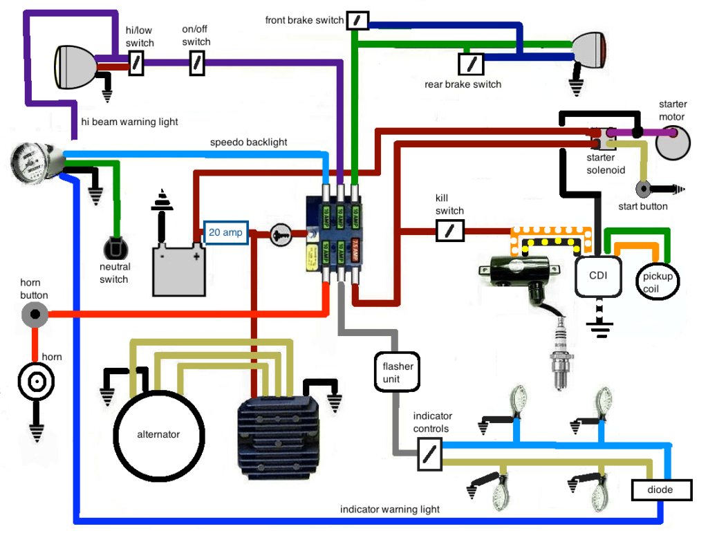
Diagrams of ignition wiring show the various wires utilized to power the vehicle’s various parts. Each component is equipped with four distinct color-coded connections. Red is for accessories while yellow is the battery, and green is for the starter solenoid. The “IGN terminal” is used to provide power to the wipers along with other operational functions. The diagram illustrates how to connect ACC or ST terminals, and other.
The battery is connected to the terminal named BAT. The electrical system cannot start without the battery. A dead battery could make the switch stop turning on. The wiring diagram will tell the location of your car’s battery. The accessory terminals on your vehicle connect to the battery as well as the ignition switch. The BAT terminal is connected to the battery.
Some ignition switches feature a separate “accessory” position, where users can manage their outputs without using the ignition. Sometimes, customers would like an auxiliary output that can be used independently from the ignition. To use the auxiliary output, wire the connector in the same colors as ignition, connecting it to the ACC terminal on the switch. This is a convenient feature however it does have one major distinction. A lot of ignition switches can be programmed to have an ACC position when the vehicle is in the ACC position. They will also be in the START position after the vehicle has been moved into the IGN position.
Gallery of 2008 Chevy Malibu Ignition Wiring Diagram
Gallery of 2008 Chevy Malibu Ignition Wiring Diagram


