2009 Chevy Impala Ignition Wiring Diagram – Let’s begin by looking at the various types of terminals on an ignition switch. These are terminals for the Ignition, Coil, or Accessory. Once we have identified the terminals that are utilized, we can begin to determine the various components of the 2009 Chevy Impala Ignition Wiring Diagram. We’ll also go over the roles of the Ignition switch and the Coil. Following that, we will proceed to the Accessory Terminals.
Terminals for the ignition switch
An ignition switch is comprised of three switches. They feed the battery’s voltage to many different locations. The first switch supplies power to the choke when it is pushed. The third is the position of the ignition switch’s ON/OFF. Different manufacturers have different colors-coding systems to match the conductors. OMC uses the same method. Connectors can be attached to the ignition switch in order to connect an electronic Tachometer.
Although most ignition switch terminals are duplicated, the numbers may not match the diagram. Check the electrical continuity first to ensure that they’re properly connected to the ignition switch. This can be done with a simple multimeter. After you’re satisfied with the integrity of the wires, connect the new connector. The wiring loom of an ignition system switch that is supplied by the manufacturer differs.
Before connecting the ACC outputs to your car’s auxiliary outputs It is essential to be familiar with the fundamentals of these connections. The ACC terminals and IGN terminals are the standard connections for your ignition switch. The START and IGN connections are the primary connections for stereo and radio. The ignition switch controls the car’s engine. Older cars are equipped with ignition switch terminals marked “ACC” or “ST” (for individual magnetowires).
Terminals for coil
Understanding the terminology is the first step in knowing what type of ignition coil you own. A basic diagram of the wiring will reveal a variety of connections and terminals. Each coil comes with its own operating voltage. To determine what kind of coil you’ve got first, you need to check the voltage at the S1 primary terminal. To determine if the coil is a Type A, C or B coil you must also test the resistance on S1’s.
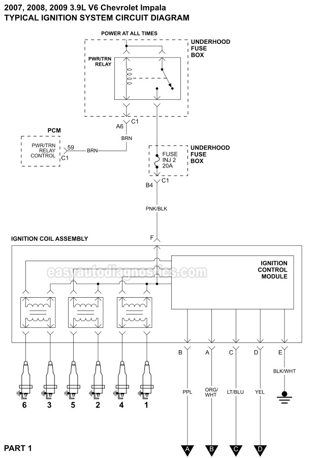
The negative end of the chassis should be connected to the coil’s low-tension end. This is what you see on the diagram of wiring. The high-tension end supplies positive direct to the sparkplugs. To prevent noise, the coil’s metal body must be connected to chassis. However, it is not necessary to electrically connect. The wiring diagram of the ignition will demonstrate how to connect the terminals of the positive or negative coils. Sometimes, a defective ignition coil can be identified through a scan performed at an auto repair shop.
The black-and-white-striped wire from the harness goes to the negative terminal. The white wire is the other one. It has a black trace, and connects to the positive terminal. The contact breaker is attached to the black wire. If you’re not sure about the connections of the two, try using an old paper clip to take them from the housing of the plug. Make sure the terminals aren’t bent.
Accessory terminals
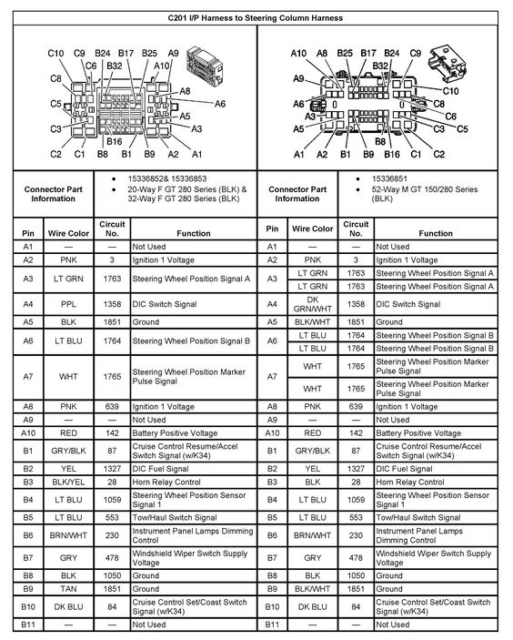
Diagrams of the ignition wiring show the wires used to power various parts of the vehicle. Each component has four distinct colored connections. For accessories, red is for starter solenoid, yellow for battery, and blue for accessory. The “IGN” terminal is used to start the vehicle and control the wipers, as well as other operating functions. The diagram below shows how to connect the ACC terminal as well as the ST terminals to various components.
The terminal BAT holds the battery. Without the battery the electrical system can not get started. The switch won’t be able to turn off if the battery isn’t there. The wiring diagram will show the location of the battery in your car. The ignition switch and the battery are connected by the accessory terminals. The BAT terminal is connected to the battery.
Certain ignition switches have an additional “accessory” position, in which users can manage their outputs with no ignition. Some customers might want to use the auxiliary input separately from the ignition. You can utilize the additional input by connecting the connector to the ACC terminal. This is a useful feature, but there is one important difference. The majority of ignition switches are designed to display an ACC status when the vehicle is in the ACC or START positions.
Gallery of 2009 Chevy Impala Ignition Wiring Diagram
Gallery of 2009 Chevy Impala Ignition Wiring Diagram


