3 Pin Ignition Coil Wiring Diagram – In the beginning, we’ll examine the various types of terminals in the ignition switch. These are the terminals used that are used for Coil, Ignition Switch, and Accessory. After we’ve identified the purpose of these terminals, we can determine the various components of the ignition wiring. We’ll also go over the roles of the Ignition switch and Coil. Next, we’ll discuss the functions of the Ignition switch as well as Coil.
Ignition switch terminals
Three switches can be found on the ignition switch. Each of the three switches is able to feed the battery’s voltage to a variety of destinations. The ON/OFF position of the switch that controls the ignition is managed by the first switch, which supplies the choke with power when it’s pushed. Different manufacturers use different colors for various conductors. This is explained in another article. OMC utilizes this method. A tachometer adapter is installed on the ignition switch, allowing the installation of a tonometer.
Although the majority of ignition switch terminals do not have an initial number, they could have a different one. Check the continuity of all wires to ensure that they are properly connected to the ignition switches. This can be checked with a simple multimeter. When you’re satisfied that all wires are running in good harmony and you are able to connect the new connector. The wiring loom used in the ignition system switch supplied by the manufacturer is different.
Before connecting the ACC outputs to the auxiliary outputs of your car It is essential to know the fundamentals of these connections. The ACC and IGN connectors are the default connections for the ignition switch. The START, IGN, and ACC terminals are primary connections to the radio or stereo, the START/IGN terminals are the most important ones. The ignition switch turns the car’s engine on and OFF. Older cars have the ignition switch’s terminals that are labeled “ACC” or “ST” (for individual magnetowires).
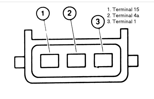
Terminals for coil
The first step in determining the type of ignition coil is to know the terminology employed. A basic diagram of the wiring will provide you with a range of connections and terminals. Each coil is operating at a certain voltage. The first step to determine which kind of coil you have is to check the voltage on S1, or the primary terminal. S1 should also be tested for resistance to determine if the coil is an A, Type B or an A coil.
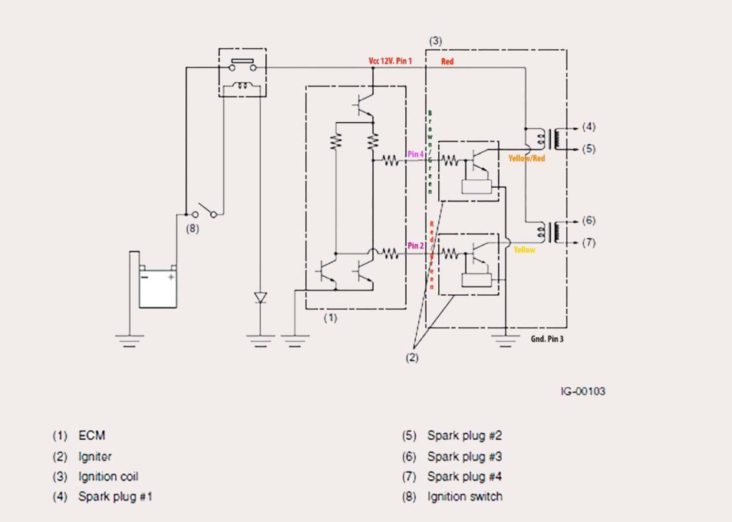
The chassis’ negative should be connected to connect the coil’s low-tension side. This is also the ground in the wiring diagram for ignition. The high-tension component supplies the spark plugs with positive. To reduce the noise, the coil’s body metal is required to be connected to the chassis. It’s not necessary for electrical use. There are also connections of the positive and negative coil terminals on the diagram of the ignition wiring. In certain cases scanning the local auto parts store will be able to diagnose malfunctioning ignition coils.
The black-and-white-striped wire from the harness goes to the negative terminal. The other white wire is black with a trace on it, and connects to the positive terminal. The contact breaker is attached to the black wire. To test the wires’ connections, use a paperclip to lift them from the housing. You should also check to make sure that the connections are not bent.
Accessory terminals
The ignition wiring diagrams illustrate the different wires used to are used to power various components of the vehicle. Typically, there are four different colored terminals for each part. Red is for accessories and yellow is for the battery, while green is the solenoid for starters. The “IGN” terminal is used to turn on the vehicle and control the wipers, as well as other operating functions. The following diagram illustrates how to connect the ACC terminal and ST terminals to various components.
The battery is attached to the terminal whose name is BAT. The electrical system is not able to begin without the battery. Furthermore, the switch won’t begin to turn on. You can refer to your wiring diagram if you are uncertain about where the car’s batteries are. Your car’s accessory terminals are connected to the ignition switch as well as the battery. The BAT connector is connected to the battery.
Certain ignition switches have an additional position. This allows users to connect their outputs to another location without having to turn on the ignition. Customers may want to utilize the auxiliary output separately from the ignition. You can use the secondary output by connecting the connector to an ACC terminal on the switch using the same colors. While this is an excellent option, there’s a thing you should know. The majority of ignition switches are set to have an ACC position when the vehicle is in the ACC position, whereas they’re set to the START position when the vehicle is in the IGN position.
Gallery of 3 Pin Ignition Coil Wiring Diagram
Gallery of 3 Pin Ignition Coil Wiring Diagram


