3 Pole Ignition Switch Wiring Diagram – First, we will examine the various types of terminals found in the ignition switch. These are terminals for the Ignition, Coil, or Accessory. After we’ve identified what these terminals are, we will identify the different parts in the ignition wiring. We will also talk about the functions and the Coil. We will then concentrate on the accessories terminals.
Terminals for the ignition switch
Three switches are located on an ignition switch. Each of these switches transmits the battery’s current to various places. The first switch is the one that supplies power to the choke, while the second switch controls the status of the ignition switch. Different manufacturers employ various color codes for the various conductors. This is discussed in another article. OMC follows this scheme. There is a connector inside the ignition switch for attaching an to a tachometer.
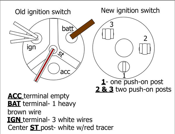
While the majority of the ignition switch terminals are not original, the numbers for each one may not be in line with the diagram. To ensure that the wires are correctly connected to the switch you must verify their continuity. You can check this using an inexpensive multimeter. After you’ve confirmed the continuity of the wires you are able to connect the connector. If your vehicle has an original factory-supplied ignition switch (or an electrical loom), the wiring loom will differ from the one in the car.
Knowing how the ACC outputs are connected to the other outputs of your car is essential. The ACC terminals and IGN terminals are the primary connections to the ignition switch. The START and IGN connections are the most important connections for stereo and radio. The ignition switch is responsible to turn the engine of your car on and off. Older cars are identified with the initials “ACC”, “ST”, (for individual magneto cables) at the ignition switch’s terminals.
Terminals for coil
The first step to determine the type of ignition coil is to understand the terminology used. A basic diagram of the wiring will provide you with a range of terminals and connections. Each coil operates at a specific voltage. The first step in determining which kind of coil you’re using is to examine the voltage of S1 or the primary terminal. To determine if it is an A, C or B coil, it is recommended to also check the resistance of S1.
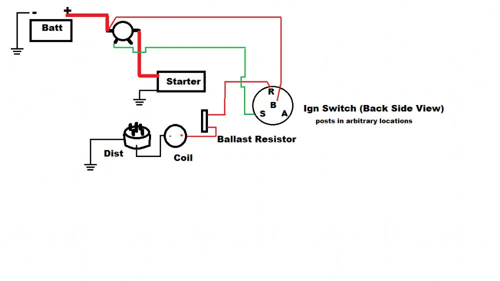
The lower-tension side of the coil needs to be connected to the chassis”negative. It is also the ground for the diagram of ignition wiring. The high-tension part connects the spark plugs to a positive. It is required to suppress the metallic body of the coil is connected to its chassis however, it is not necessary. The wiring diagram of the ignition will demonstrate how to connect the terminals of the negative or positive coils. Sometimes, a defective ignition coil can be identified with a scan in an auto parts shop.
The black-and-white-striped wire from the harness goes to the negative terminal. The other white wire is black-colored and connects to the terminal opposite. The contact breaker is connected to the black wire. You can examine the connections with a pencil to remove the wires of the housing. Also, make sure to check that the terminals haven’t been bent.
Accessory terminals
The diagrams for ignition wiring illustrate the wiring used in the power supply of the vehicle. There are generally four colors-coded terminus of each part. The red symbol represents accessories, yellow represents the battery and green is for the solenoid for starters. The “IGN” terminal is used to turn on the car, operate the wipers, and other features. This diagram shows how to connect ACC and ST terminals to the other components.
The terminal BAT is the connection for the battery. Without the battery, the electrical system does not begin. Additionally, the switch doesn’t turn on. To locate your car’s battery, check your wiring diagram. The accessory terminals in your car are connected to the ignition switch, as well as the battery. The BAT terminal is connected to the battery.
Certain ignition switches have an accessory setting where users can alter their outputs and manage them without needing to use the ignition. Users may wish to utilize the auxiliary output separately from the ignition. You can utilize the auxiliary input by connecting it to the ACC terminal. Although this is a great feature, there’s something to be aware of. Most ignition switches are set to operate in the ACC position when the car is in the ACC position, while they’re in the START position when the car is in the IGN position.
Gallery of 3 Pole Ignition Switch Wiring Diagram
Gallery of 3 Pole Ignition Switch Wiring Diagram


