3 Position Ignition Switch Wiring Diagram – First, we will look at the various types of terminals for the ignition switch. These are terminals for the Ignition, Coil, or Accessory. After we’ve identified the terminals used then we can identify the different components of the 3 Position Ignition Switch Wiring Diagram. In addition, we will discuss the function of the Ignition switch and Coil. Following that, we’ll shift our attention to the Accessory terminals.
Terminals for ignition switches
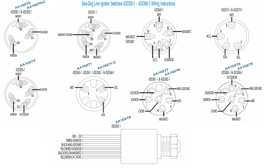
Three switches can be found on the ignition switch. Each of these three switches is able to feed the battery’s voltage to several different destinations. The choke is powered by the first switch. The third switch regulates the ON/OFF of the ignition switch. Each manufacturer has its own color-coding system, which we’ll discuss in a subsequent article. OMC uses this method. Connectors can be attached to the ignition switch to add the digital Tachometer.
Even though some of the ignition switch terminals might not be authentic, the numbering of each may not match the diagram. It is important to first verify the integrity of the wires to see if they are connected to the correct ignition switch. This can be done with a simple multimeter. Once you are satisfied that all wires are in good continuity then you can connect the new connector. If your car is equipped with an original ignition switch supplied by the factory (or an electrical loom) the wiring loom may differ from that in your vehicle.
It is important to understand how the ACC outputs and auxiliary outputs work in order to connect them. The ACC and IGN connectors are the standard connections of your ignition switch. The START, IGN, and ACC terminals are the primary connections for radios or stereo, the START/IGN connections are the main ones. The ignition switch switches the engine of your car ON and OFF. The ignition switch terminals on older cars are identified with the letters “ACC” as well as “ST” (for the individual magneto wires).
Terminals for coil
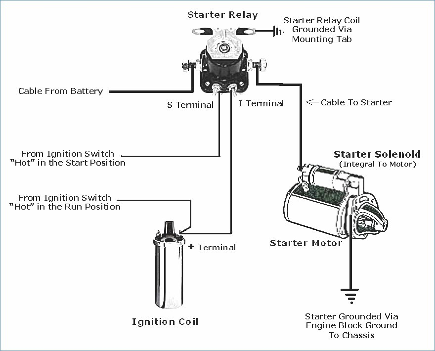
The first step in determining the kind of ignition coil is to know the terminology that is used. The fundamental diagram of ignition wiring illustrates a variety of connections and terminals. There are two primary and one secondary. The voltage that operates on each coil differs. Therefore, it is important to first test the voltage at S1 (primary terminal). S1 should also be checked for resistance to determine if the coil is a Type B, B or A coil.
The chassis’ negative must be connected to the low-tension side. This is the ground of the wiring for ignition. The high-tension side provides positive direct to the sparkplugs. To reduce the noise the coil’s body metal must be connected with the chassis. This is not necessary for electrical use. The wiring diagram for the ignition will show you how to connect the terminals of either the negative or positive coils. In some instances, you’ll find that an ignition coil that is malfunctioning can be diagnosed with scans at an auto parts shop.
The black-and-white-striped wire from the harness goes to the negative terminal. The white wire is black-colored and connects to the terminal opposite. The black wire goes to the contact breaker. You can check the connections using a paperclip to take the wires out of the housing. It’s also crucial to make sure that the terminals don’t bend.
Accessory terminals
Diagrams of the ignition wiring show the wires used to provide power to various components of the vehicle. There are generally four colored terminus lines for each component. To identify accessories, red stands for starter solenoid, yellow is for battery and blue for accessories. The “IGN” terminal is used to start the vehicle, controlling the wipers and various other functions. This diagram shows how you can connect ACC and ST terminals with the other components.
The battery is connected to the terminal called BAT. The battery is vital for the electrical system to get started. A dead battery could cause the switch to stop turning on. It is possible to view your wiring diagram to determine where your car’s batteries are placed. The accessory terminals in your car are connected to the ignition switch and the battery. The BAT Terminal is connected to the battery.
Some ignition switches come with an additional “accessory position” which allows users to adjust their outputs independently of the ignition. Some customers may prefer to use the auxiliary output in addition to the ignition. To allow the auxiliary output to be used, plug in the connector in the same color as the ignition. Then , connect it to the ACC end of the switch. While this is a convenient feature, there is one important difference. Most ignition switches come with an ACC position when your vehicle is in the ACC mode and a START position when the switch is in IGN.
Gallery of 3 Position Ignition Switch Wiring Diagram
Gallery of 3 Position Ignition Switch Wiring Diagram


