3000gt Ignition Wiring Diagram – Let’s first take a look at the different types of terminals on the ignition switch. These include terminals that are used for Coil, Ignition Switch, and Accessory. After we’ve identified the terminals used, we can begin to recognize the various parts of the 3000gt Ignition Wiring Diagram. We will also cover the functions of both the Ignition Switch and the Coil. Then, we’ll talk about the roles of the ignition switch and Coil.
The terminals of the ignition switch
The ignition switch consists of three switches. These are responsible for feeding the battery’s energy to various locations. The first switch supplies power to the choke when it is pushed. The third is the position of the ignition switch’s ON/OFF. Different manufacturers use different color-coding methods to identify different conductors. This will be covered in another article. OMC uses the same method. The ignition switch also includes an adapter for the addition of an tachometer.
Although the majority of ignition switch terminals may not be original, the numbers for each might not be consistent with the diagram. Before you plug into the ignition switch, be sure to test the continuity. A simple multimeter will assist you in this. Once you’re satisfied with the quality of the connection, you can place the new connector. If your car has an original ignition switch supplied by the factory (or an electrical loom), the wiring loom might differ from that in your car.
It is important to know the differences between the ACC and secondary outputs. The ACC terminals and IGN terminals serve as the standard connections for your ignition switch. The START and IGN connections are the most important connections for stereo and radio. The ignition switch is accountable to turn the car’s engines on and off. The terminals of the ignition switch on older cars are identified with the alphabets “ACC” and “ST” (for the individual magneto wires).
Terminals for coil
The first step in determining the kind of ignition coil is to comprehend the terms employed. The diagram of the basic ignition wiring shows a number different connections and terminals. There are two primary and secondary connections. The operating voltage of each coil differs. Therefore, it is important to first test the voltage at the S1 (primary terminal). S1 must also be inspected for resistance to determine if it’s an A, Type B or A coil.
The coil’s low-tension side must be connected with the chassis positive. This is also the ground on the diagram of the ignition wiring. The high-tension part is a positive connection to the sparkplugs. To prevent noise, the coil’s metal body is required to be connected to the chassis. But, it’s not required to connect electrically. The wiring diagram for ignition will also indicate the connections of the positive coil’s terminals. Sometimes, a visit to an auto parts store could diagnose a malfunctioning ignition wire.
The black-and-white-striped wire from the harness goes to the negative terminal. The positive terminal receives the other white wire with an black trace. The black wire connects to the contactbreaker. You can check the connections using a paperclip to remove the wires from the housing. It is also important to make sure that the terminals do not bend.
Accessory terminals
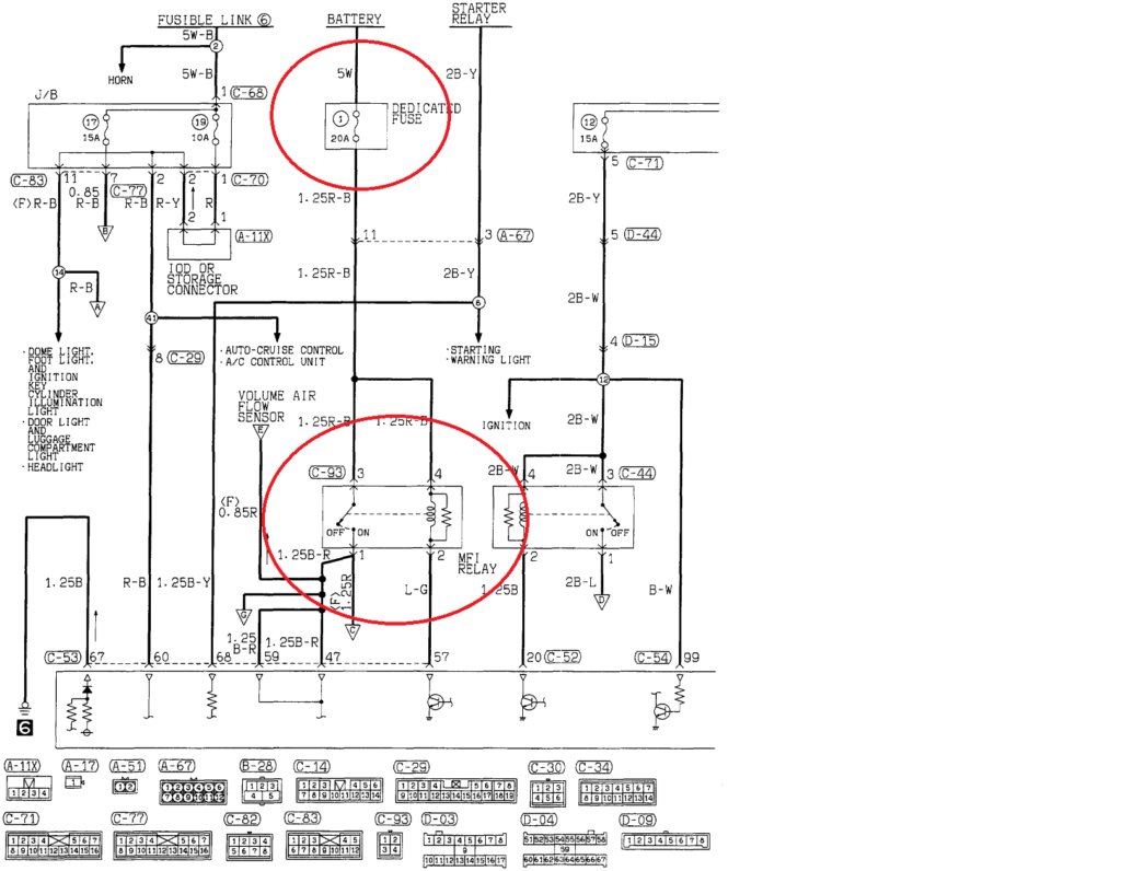
Diagrams of ignition wiring show the wires used to supply power to different parts of the vehicle. Each part has four distinct colored connections. The red color is used for accessories and yellow is for the battery, while green is the starter solenoid. The “IGN terminal is used to start the car, controlling the wipers and other functions. The following diagram shows how to connect the ACC terminal as well as the ST terminals to the other components.
The terminal BAT is the connector for the battery. The electrical system can’t be started without the battery. A dead battery can make the switch not come on. A wiring diagram can inform you where to find your car’s battery. The accessory terminals of your car connect to the battery as well as the ignition switch. The BAT terminal is connected to the battery.
Certain ignition switches come with an “accessory” position that allows users to control their outputs without needing to utilize the ignition. Sometimes, customers want to make use of an additional output that is not connected to the ignition. Make use of the additional output by connecting it to an ACC terminal on your switch using the same colors. This is an excellent feature, but there is one important difference. The majority of ignition switches are set to be in an ACC position when the vehicle is in the ACC position, whereas they’re in the START position when the vehicle is in the IGN position.
Gallery of 3000gt Ignition Wiring Diagram

Gallery of 3000gt Ignition Wiring Diagram


