4 Pin Ignition Coil Wiring Diagram – Let’s begin by examining the different kinds and functions of terminals found in the ignition switches. These are terminals that are used for Coil, Ignition Switch, and Accessory. Once we know what these terminals do then we can identify the different parts in the ignition wiring. We’ll also discuss the function of the Ignition switch, and Coil. The next step is to focus to the accessory terminals.
Terminals for ignition switches
An ignition switch is comprised of three switches. They feed the voltage of the battery to different locations. The first switch provides power to the choke while the second toggles the ON/OFF status of the ignition switch. Different manufacturers utilize their own color-coding method for the various conductors, which is explained in a different article. OMC follows this scheme. A connector can be added to the ignition switch to add the digital Tachometer.
While the majority of the ignition switch terminals may not be original, the numbers for each might not be consistent with the diagram. Check the continuity of all wires to make sure they’re properly connected to the ignition switches. This can be checked using a cheap multimeter. After you’re satisfied with the continuity it’s time to connect the new connector. If you are using an ignition switch that is supplied by the manufacturer the wiring loom may be distinct from the one that is in your car.
It is essential to know the ways in which the ACC outputs and the auxiliary outputs function to connect them. The ACC and IGN connectors are the default connections for your ignition switch. Although the START, IGN, and ACC terminals are the main connections to the radio or stereo, the START/IGN connections are the most important ones. The ignition switch controls the car’s engine. Older cars are identified with the letters “ACC”, “ST”, (for individual magneto cables) at their ignition switch’s terminals.
Terminals for coil
To determine the type of ignition coil, the first step is to understand the definition of. You’ll see a number of connections and terminals within a basic ignition wiring schematic that include two primary and two secondary. Each coil comes with its own operating voltage. To determine which type of coil you’ve got, the first step is to test the voltage at S1, which is the primary terminal. S1 must also go through resistance tests to determine if it’s an A or B coil.
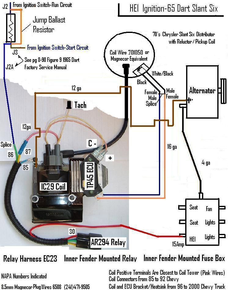
The chassis’ negative end should be connected to connect to the coil’s lower-tension end. This is what’s called the ground in the diagram of the ignition wiring. The high-tension part provides positive direct to the sparkplugs. For suppression purposes the body of the coil must be connected to the chassis. It is not necessary to electrically connect. A wiring diagram can depict the connection between positive and negative coil terminals. Sometimes, a visit to an auto part store can diagnose a malfunctioning ignition wire.
The black-and-white-striped wire from the harness goes to the negative terminal. The terminal that is negative is served by the trace in black that’s connected to the white wire. The black wire connects with the contact breaker. To confirm the connections, employ a paperclip, or a pencil to pull them out of the housing for the plug. Be sure the terminals do not bend.
Accessory terminals
Diagrams of the ignition wiring illustrate the wires that provide power to various components of the car. In general, there are four different colored terminals for each part. Red is for accessories, yellow is for the battery, and green is the starter solenoid. The “IGN” terminal lets you start the car, control the wipers or other operation features. The diagram illustrates how to connect ACC or ST terminals and the rest.
The battery is attached to the terminal named BAT. The electrical system won’t start if the battery isn’t connected. Furthermore, the switch doesn’t turn on. The wiring diagram will tell you where to find your car’s battery. The accessory terminals in your car are connected to the ignition switch, as well as the battery. The BAT terminal is connected with the battery.
Some ignition switches have the “accessory” setting that permits users to regulate their outputs without needing to turn on the ignition. Sometimes, users want to use an auxiliary output independent of the ignition. For the auxiliary output to be used, plug in the connector to the same color as that of the ignition. Connect it to the ACC end of the switch. This feature is convenient however it does have one key distinction. Most ignition switches are configured to have an ACC status when the vehicle is in the ACC or START position.
Gallery of 4 Pin Ignition Coil Wiring Diagram
Gallery of 4 Pin Ignition Coil Wiring Diagram


