5 Wire Ignition Switch Wiring Diagram – Let’s first examine the various terminals on the ignition switch. These are the terminals that connect the Ignition, Coil, or Accessory. Once we’ve determined the function of the terminals we can determine the various components of the ignition wiring. Then, we will discuss the functions and the Coil. Then, we’ll turn our attention to Accessory terminals.
Terminals for ignition switches
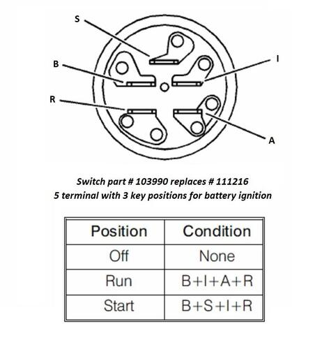
An ignition switch is composed of three different switches. These are responsible for supplying the battery’s energy to various places. The ON/OFF state of the switch that controls the ignition is managed by the third switch, which supplies power to the choke when it is pushed. Different manufacturers use various color codes for the different conductors. This is discussed in a separate article. OMC follows the same system. A tachometer adapter is installed on the ignition switch, allowing for the addition of an tachometer.
While the majority of ignition switch terminals don’t have the original design, the numbering may not be in line with the diagram. Verify the integrity of the wires first to ensure they are correctly plugged in the ignition switch. This can be done with a multimeter that is inexpensive. Once you’re satisfied about the continuity of the wires, then you’ll be able to install the new connector. If you have an ignition switch supplied by the manufacturer the wiring loom will be different from the one in your car.
It is important to understand the way that ACC outputs and auxiliary outputs work in order to connect them. The ACC, IGN and START terminals are the default connections to the ignition switch. They also serve as the primary connections to your radio and stereo. The ignition switch’s function is to turn the car’s engines on and off. Older vehicles have ignition switch terminals labeled “ACC” or “ST” (for individual magnetowires).
Terminals for coil
To determine the type of ignition coil you need to know the step is to know the definition of. A basic ignition wiring diagram will reveal a variety of terminals and connections, including two primary and two secondaries. Each coil is equipped with a distinct operating voltage. To determine what kind of coil you own first, you need to determine the voltage at the S1 primary terminal. To determine whether it’s an A, C or B coil you must also test S1’s resistance.
The chassis’ negative needs to be connected to the low-tension side. This is the wiring diagram you will find in the wiring diagram. The high-tension supply provides positively directly to spark plugs. It is necessary to suppress the coil’s metallic body be connected to its chassis, however it isn’t essential. The wiring diagram for the ignition will explain how to connect the terminals of either the positive and negative coils. In some instances, you’ll find that the ignition coil is damaged and can be diagnosed with a scan at an auto parts shop.
The black-and-white-striped wire from the harness goes to the negative terminal. The white wire is the other one. It has a black trace, and it connects to the positive terminal. The black wire is connected to the contact breaker. You can take the black wire from the housing of the plug using a paper clip in case you are uncertain about the connections. It’s also crucial to ensure that the terminals do not bend.
Accessory Terminals
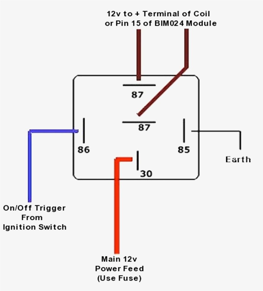
Diagrams of ignition wiring depict the wires that are used to power the vehicle’s electrical supply. There are typically four terminals with color codes that are connected to the component. The red color represents accessories, yellow represents the battery and green for the solenoid for starters. The “IGN” terminal can be utilized to turn on the car, control the wipers and other features. The diagram shows the connections to the ACCand ST terminals.
The terminal BAT is the connection for the battery. The electrical system won’t start in the event that the battery isn’t connected. Additionally, the switch will not be able to turn on without the battery. It is possible to view your wiring diagram to determine where the batteries of your car are placed. The ignition switch as well as the battery are connected via accessory terminals. The BAT connector is connected to the battery.
Some ignition switches offer the option of an “accessory position” that allows users to alter their outputs without the ignition. Sometimes, customers wish to make use of the auxiliary output separate from the ignition. You can utilize the auxiliary input by connecting the connector to the ACC terminal. This is a convenient feature however, it does have one key difference. Some ignition switches are configured to be in an ACC position when the vehicle is in the ACC position. They also will be in START mode once the vehicle is entered the IGN position.
Gallery of 5 Wire Ignition Switch Wiring Diagram
Gallery of 5 Wire Ignition Switch Wiring Diagram


