6 Wire Generator Ignition Switch Wiring Diagram – Let’s first examine the different types and purposes of the terminals that are found in the ignition switches. These are the terminals for the Ignition, Coil, or Accessory. Once we have established the purpose of these terminals are for then we can determine the various parts of the 6 Wire Generator Ignition Switch Wiring Diagram. We’ll also go over the functions of the Ignition switch and Coil. The next step is to focus to the accessory terminals.
Terminals for ignition switches
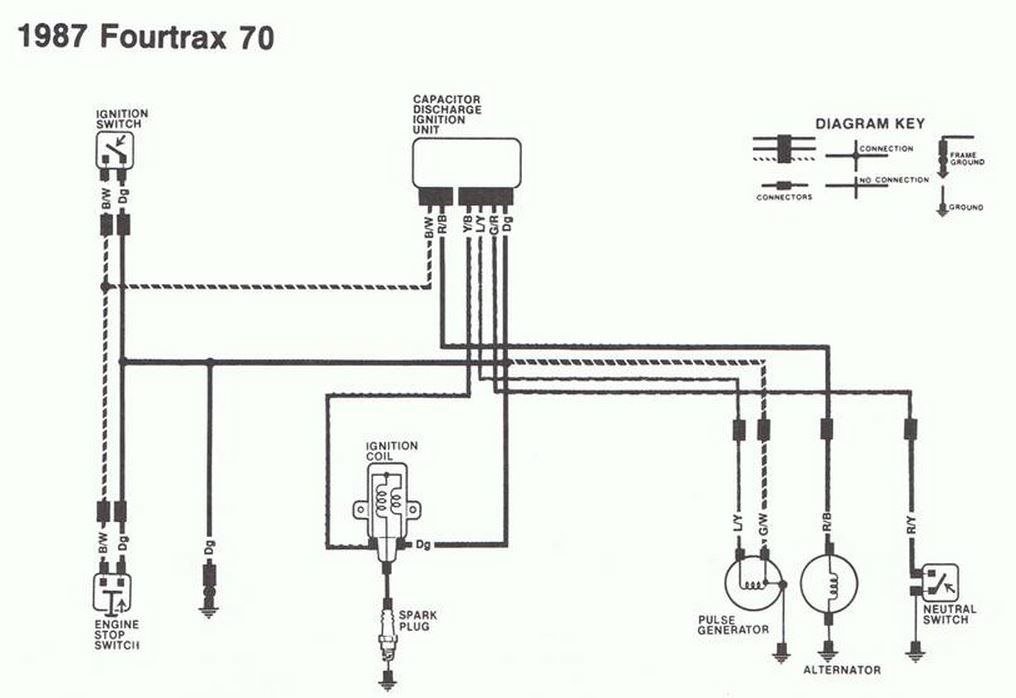
An ignition switch is made up of three different switches. These are the ones that supply the battery’s energy to various places. The choke is powered by the first switch. The second switch is responsible for the ON/OFF of the ignition switch. Different manufacturers use their own color-coding systems for the various conductors, which is explained in a different article. OMC follows this scheme. There is a connector inside the ignition switch for connecting an tachometer.
Although some ignition switch terminals don’t come in original form however, the numbers may not match the diagram. You should first check the integrity of the wires to see if they are plugged into the correct ignition switch. This can be done with a simple multimeter. When you are satisfied with the integrity of the wires you can connect the new connector. If your vehicle is equipped with an ignition switch that is installed the wiring diagram will differ.
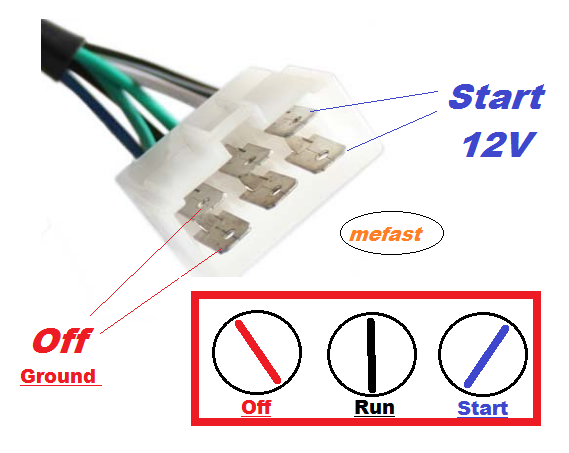
The first step is to understand the distinctions between ACC and the auxiliary outputs. The ACC/IGN terminals act as the default connections for the ignition switch. The START/IGN connections connect to the radio or stereo. The ignition switch is responsible for turning the car’s engine on and off. The terminals of the ignition switch on older vehicles are marked with the alphabets “ACC” as well as “ST” (for individual magneto wires).
Terminals for coil
To determine the type of ignition coil, the first step is to understand the terminology. You’ll see a number of connections and terminals within an ignition wiring schematic that include two primary and two secondary. Each coil has an operating voltage. The first step in determining which kind of coil you’re using is to examine the voltage of S1 or the primary terminal. S1 should also undergo resistance testing to determine whether it’s a Type A or B coil.
The chassis’ negative must be connected to the side of low-tension. It is also the ground on the diagram of ignition wiring. The high-tension end provides positive direct to the sparkplugs. To prevent noise the body of the coil is required to be connected to the chassis. But, it’s not necessary to electrically connect. The diagram for the ignition wiring will also show you the connection of the positive and negative coil terminals. In some cases, a scan at the local auto parts store can help you identify defective ignition coils.
The black-and-white-striped wire from the harness goes to the negative terminal. The positive terminal receives the other white wire, which has an trace of black. The black wire is connected to the contactbreaker. To check the connection, employ a paperclip, or a pencil to lift them out from the plug housing. Be sure that you don’t bend the connectors.
Accessory terminals
Diagrams of ignition wiring show the different wires that are utilized to power the vehicle’s various parts. Each component is equipped with four distinct connections that are color coded. Red stands for accessories, yellow is for the battery and green for the solenoid for starters. The “IGN” terminal can be used to turn on the car, control the wipers, as well as other features. The following diagram illustrates how to connect the ACC terminal as well as the ST terminals to the other components.
The terminal BAT is the connector for the battery. Without the battery the electrical system will not begin. The switch won’t turn off if the battery isn’t present. You may refer to the wiring diagram if unsure where your car’s batteries are. The accessory terminals in your vehicle are connected to the battery as well as the ignition switch. The BAT terminal connects to the battery.
Certain ignition switches come with the “accessory” position that allows users to control their outputs , without needing to utilize the ignition. Customers sometimes want the auxiliary output to be used separately from the ignition. In order to use the auxiliary output, wire the connector with the same colors as the ignition, and connect it to the ACC terminal on the switch. This is a great convenience feature however there’s a distinction. A lot of ignition switches can be set to have an ACC position once the car has been moved into the ACC position. They also will be in START mode after the vehicle has been entered the IGN position.
Gallery of 6 Wire Generator Ignition Switch Wiring Diagram

Gallery of 6 Wire Generator Ignition Switch Wiring Diagram


