7 Pin Ignition Switch Kawasaki Ninja Ignition Wiring Diagram – The first step is to examine the various terminals that are used in the ignition switch. These are the terminals used for Coil, Ignition Switch, and Accessory. Once we’ve established the purpose of these terminals, we can identify the various parts of the ignition wiring. We will also talk about the functions and the Coil. After that, we will focus on the accessory terminals.
Terminals for the ignition switch
There are three different switches on the ignition switch, and they feed the battery’s voltage to a variety of locations. The ON/OFF state of the ignition switch is controlled by the third switch, which delivers the choke with power when it is pushed. Different manufacturers have different color-coding systems for different conductors. We’ll discuss this in a separate article. OMC follows this method. The adapter is attached to the ignition switch that allows the addition of an tonometer.
While most ignition switch terminals are not authentic, the numbering of each one may not be in line with the diagram. It is important to first verify the continuity of the wires to determine if they’re connected to the ignition switch correctly. A cheap multimeter can help you do this. Once you’ve verified the integrity of the wires you can then install the connector. If you have an ignition switch supplied by the manufacturer the wiring loom will be different from the one in your car.
Before you can connect the ACC outputs to your car’s auxiliary outputs, it is important to understand the basics of these connections. The ACC and IGN terminals are the default connection on your ignition switch. the START and IGN terminals are the main connections for the stereo and radio. The ignition switch switches the car’s engine on and OFF. On older cars the terminals of the ignition switch are marked with the letters “ACC” as well as “ST” (for individual magnetic wires).
Coil terminals
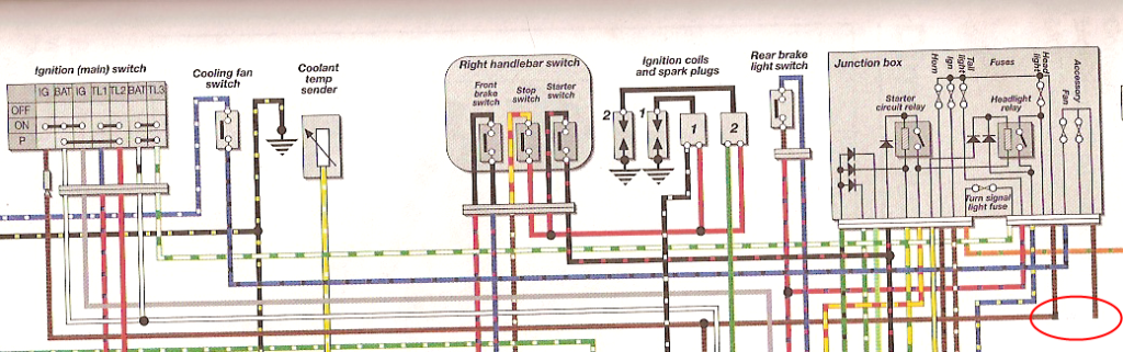
The first step in determining the kind of ignition coil is to know the terms used. A simple diagram of the wiring will reveal a variety of connections and terminals, comprising two primary and two secondary. Each coil is operating at a certain voltage. The first step to determine which kind you have is to check the voltage at S1 or the primary terminal. To determine if it is an A, C, or B coil, it is recommended to also test the resistance on S1’s.
The negative end of the chassis end should be connected to to the coil’s lower-tension end. This is what is known as the ground for the wiring for ignition. The high tension side supplies positive power directly to the spark plugs. It is essential for suppression purposes that the metallic body of the coil is connected to the chassis, however, it is not necessary. The diagram of the ignition wiring will also show you the connections between the negative and positive coil’s terminals. In some cases it is recommended to conduct a scan at your local auto parts shop will help identify defective ignition coils.
The black-and-white-striped wire from the harness goes to the negative terminal. The negative terminal is served by the black trace connected to the white wire. The black wire connects to the contactbreaker. To test the wires’ connections, use a paperclip to lift them out of the housing. Be sure the terminals don’t bend.
Accessory terminals
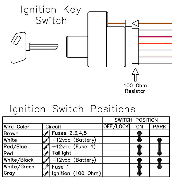
The ignition wiring diagrams show the various wires that are used to power the various components. There are usually four color-coded terminals that correspond to the respective component. To identify accessories, red is the starter solenoid’s color, yellow is for battery and blue for accessory. The “IGN terminal” is used to run the wipers, as well as other operating functions. The diagram shows the connection of the ACCand ST terminals.
The battery is attached to the terminal called BAT. The electrical system cannot begin without the battery. The switch won’t be able to turn off if the battery isn’t present. If you’re not sure of the exact location where the battery in your car is located, you can review your wiring diagram to see how to locate it. The ignition switch is connected to the car’s battery. The BAT terminal is connected to the battery.
Some ignition switches have the “accessory” setting that permits users to control their outputs without needing to utilize the ignition. Customers sometimes want the auxiliary output to be used independently from the ignition. You can use the secondary input by connecting it to the ACC terminal. While this is an excellent feature, there’s something to be aware of. A majority of ignition switches feature an ACC position when your vehicle is in ACC mode and a START mode when you are in IGN.
Gallery of 7 Pin Ignition Switch Kawasaki Ninja Ignition Wiring Diagram
Gallery of 7 Pin Ignition Switch Kawasaki Ninja Ignition Wiring Diagram


