8n Ford Tractor Ignition Wiring Diagram – We will first take a look at the different kinds of terminals for the ignition switch. These are the terminals that connect the Ignition, Coil, or Accessory. Once we have identified the purpose of these terminals then we can identify the different parts in the ignition wiring. Then, we will discuss the functions for the Ignition switch as well as the Coil. Then we’ll move on to the Accessory Terminals.
The terminals of the ignition switch
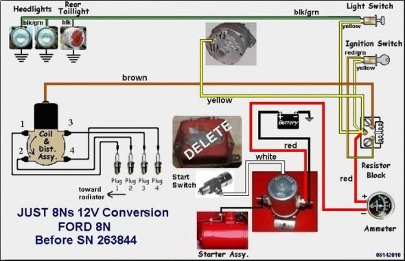
Three switches are located in an ignition switch. Each of these three switches transmits the battery’s current to several different locations. The first switch provides power to the choke whenever pushed, and the second is the ignition switch’s ON/OFF position. Different manufacturers use different color-coding methods to identify different conductors. We’ll discuss this in a separate article. OMC uses this method. This connector allows the attachment of a speedometer the ignition switch.
While the majority of the ignition switch terminals are not original, the numbers for each may not match the diagram. Before you plug into the ignition switch, be sure to test the continuity. A multimeter is a great tool to test the continuity. When you’re satisfied with the integrity of the wires, then you’ll be able to connect the new connector. If you are using a factory-supplied ignition switch the wiring loom will be different from that in your car.
Understanding how ACC outputs connect to the auxiliary outputs in your vehicle is crucial. The ACC terminals as well as the IGN terminals are the default connections to the ignition switch. The START and IGN connections are the main connections for stereo and radio. The ignition switch operates the engine’s switch to turn off or on. The terminals for the ignition switch on older vehicles are marked with the initials “ACC” as well as “ST” (for each magneto wires).
Terminals for coil
The terminology used to determine the kind and model of the ignition coil is the primary thing. A basic diagram of the wiring will reveal a variety of terminals and connections. It is essential to identify the type of coil that you own by examining the voltage at the primary terminal, called S1. S1 should also be checked for resistance to determine if the coil is an A, Type B, or A coil.
The coil’s low-tension side must be connected to the chassis’ positive. This is also the ground on the diagram of ignition wiring. The high-tension end supplies positive direct to the sparkplugs. For suppression purposes the coil’s body metal must be connected to the chassis. It’s not necessary to use electricity. You will also see the connections between the negative and positive coil terminals on the diagram of the ignition wiring. Sometimes, a malfunctioning ignition coil is identified by a scan done at an auto parts shop.
The black-and-white-striped wire from the harness goes to the negative terminal. The positive terminal receives the other white wire and a black trace. The black wire connects to the contact breaker. It is possible to remove the black wire from the plug housing by using a paperclip in case you are uncertain about the connection. You should also check to make sure that the connections aren’t bent.
Accessory terminals
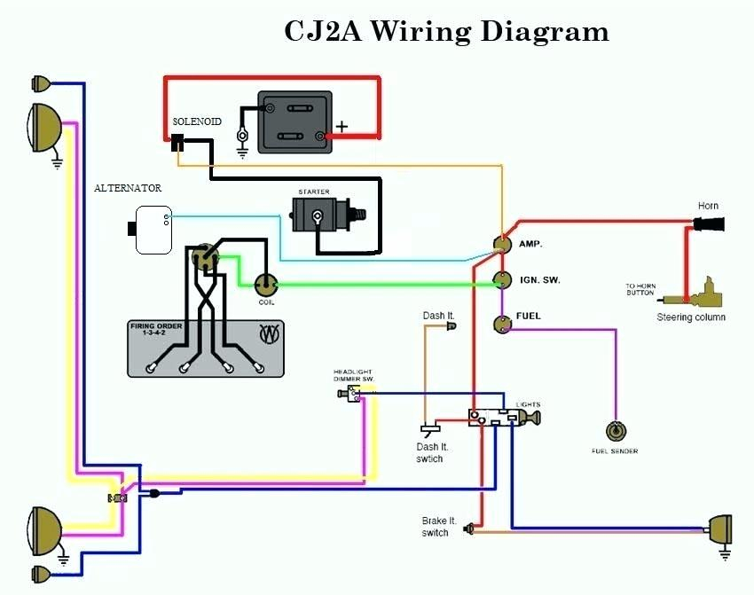
Diagrams of ignition wiring show the various wires that are used to power the various components. There are generally four colors of terminals connected to each part. The red color is for accessories, yellow to the battery and green for the starter solenoid. The “IGN terminal” is used to provide power to the wipers along with other operational functions. The diagram demonstrates how to connect the ACC and ST terminals to the rest of the components.
The terminal BAT is the connection for the battery. The battery is necessary to allow the electrical system to get started. Additionally, the switch will not turn on without the battery. If you don’t know where your car’s battery is located, you can look at the wiring diagram of your car to determine the best way to find it. The accessory terminals in your car are connected to the battery as well as the ignition switch. The BAT terminal is connected to the battery.
Certain ignition switches come with an additional position in which users can modify their outputs as well as control them without having to turn on the ignition. Some customers want the output of the auxiliary to be used separately from the ignition. To make use of the auxiliary output, wire the connector using the same colors as ignition, and connect it to the ACC terminal on the switch. Although this is a great option, there’s a thing you need to know. The majority of ignition switches are configured to display an ACC status when the car’s in either the ACC or START position.
Gallery of 8n Ford Tractor Ignition Wiring Diagram
Gallery of 8n Ford Tractor Ignition Wiring Diagram


