91 Mustang Ignition Switch Wiring Diagram – We will first look at the various types and purposes of the terminals found on the ignition switches. These include terminals that are used for Coil, Ignition Switch, and Accessory. After we’ve identified what these terminals do then we can identify the different parts in the ignition wiring. We will also talk about the functions and the Coil. After that we will move on to the Accessory Terminals.
The terminals of the ignition switch
The ignition switch consists of three switches. These are the ones that supply the battery’s power to several locations. The first switch powers the choke. The third switch regulates the ON/OFF of the ignition switch. Different manufacturers have different color-coding schemes to identify different conductors. We will cover this in another article. OMC utilizes this system. The connector allows for the connection of a speedometer to the ignition switch.
Even though many ignition switch terminals don’t come in original form, the numbering may not match the diagram. Before you plug in the ignition switch, make sure to check the continuity. A multimeter is a good tool to check the continuity. Once you’ve verified that the wires are in good condition, you can then install the connector. The wiring loom for an ignition switch that is factory-supplied will be different than the one you have in your car.
To connect the ACC outputs to the auxiliary outputs of your car, you need to understand how these two connections work. The ACC and IGN terminals are the default connections for the ignition switch. the START and IGN terminals are the primary connections for radio and stereo. The ignition switch acts as the engine’s on/off button. Older cars are identified by the initials “ACC”, “ST”, (for individual magneto cables) at the ignition switch terminals.
Terminals for coil
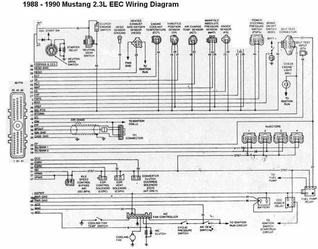
The first step in determining the kind of ignition coil is to know the terms used. The diagram of the basic ignition wiring illustrates a variety of connections and terminals. There are two primary and one secondary. The coils are equipped with a particular operating voltage. The first method of determining what type you’ve got is to check the voltage of S1 the primary terminal. S1 should also be checked for resistance to determine if it’s a Type B, B, or an A coil.
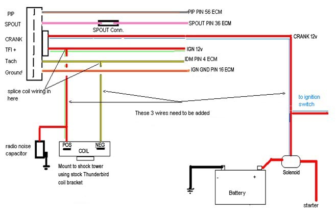
The low-tension side of the coil needs to be connected to the chassis”negative. This is also the ground in the wiring diagram for ignition. The high tension side provides positively directly to the spark plugs. The metal body of the coil needs to be connected to the chassis to prevent it from being smothered but is not electrically necessary. You will also see the connections of the negative and positive coil’s terminals on the diagram of the ignition wiring. There could be an issue with the ignition coil that is easily identified by looking it up at the auto parts shop.
The black-and-white-striped wire from the harness goes to the negative terminal. The other white wire is black and goes to the terminal opposite. The black wire is connected to the contact breaker. It is possible to remove the black wire from the housing of the plug with a paper clip if you are unsure about the connections. Make sure that the connectors don’t bend.
Accessory terminals
Diagrams of ignition wiring show the wires that are used in the power supply of the vehicle. There are usually four different colors of terminals connected to each part. The red color is for accessories, yellow to the battery and green the starter solenoid. The “IGN” terminal is used to start the car , and also to operate the wipers, as well as other operating features. This diagram shows how to connect ACC and ST terminals to the rest of components.
The terminal BAT is the connection for the battery. The electrical system will not start in the event that the battery isn’t connected. The switch will not turn off if the battery isn’t present. A wiring diagram can tell the location of the battery in your car. The accessory terminals in your car are connected with the battery as well as the ignition button. The BAT terminal is connected to the battery.
Some ignition switches feature an additional “accessory” position, in which users can manage their outputs without using the ignition. Some customers prefer to use an auxiliary output that is independent of the ignition. Make use of the auxiliary output by connecting it to an ACC terminal on the switch with the same colors. This is a great convenience feature, but there is one difference. A majority of ignition switches feature an ACC position when your car is in ACC mode, and a START position when it is in IGN.
Gallery of 91 Mustang Ignition Switch Wiring Diagram
Gallery of 91 Mustang Ignition Switch Wiring Diagram


