97 Blazer Ignition Switch Wiring Diagram – We will first look at the various kinds and functions of terminals that are found in the ignition switches. These include the terminals that are for the Ignition switch, Coil, and Accessory. Once we know the terminals that are utilized then we can recognize the various parts of the 97 Blazer Ignition Switch Wiring Diagram. Then, we will discuss the functions as well as the Coil. Then, we’ll turn our attention to the Accessory terminals.
Terminals for ignition switches
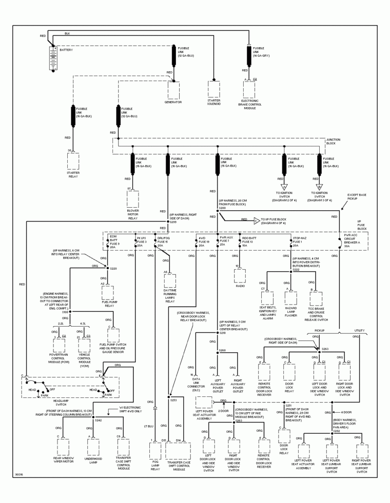
An ignition switch is composed of three different switches. These are the ones that supply the battery’s power to several destinations. The first switch is used to drive the choke by pushing it, while another switch controls the ON/OFF setting. Different manufacturers have distinct colour-coding systems that correspond to the conductors. OMC follows this system. Connectors can be connected to the ignition switch to connect the digital Tachometer.
While the majority of ignition switch terminals don’t have an original number, they might be equipped with a different number. To make sure that your wires are properly plugged in to the ignition switch, you must verify their continuity. This can be done with a cheap multimeter. When you are happy with the continuity of the wires install the new connector. The wiring loom of an ignition switch that is factory-supplied will be different than the one you have in your car.
You must first understand the ways in which the ACC outputs and auxiliary outputs work in order to join them. The ACC terminals as well as the IGN terminals are the primary connections to the ignition switch. The START and IGN connections are the primary connections for radio and stereo. The ignition switch regulates the engine in your car. Older vehicles are identified with the initials “ACC”, “ST”, (for individual magneto cables) at the ignition switch’s terminals.
Terminals for coil
Understanding the terms that is used is the initial step to determining what kind of ignition coil you need. A basic ignition wiring diagram will display a range of terminals and connections which include two primary terminals and two secondaries. The operating voltage of each coil is different. Therefore, it is important to first test the voltage at the S1 (primary terminal). To determine if it is an A, C, or B coil it is recommended to also test the resistance on S1’s.
The coil’s low-tension end must be connected with the chassis positively. This is the base of the ignition wiring. The high-tension supply delivers the spark plugs with positive electricity directly. The aluminum body of the coil needs to be connected to the chassis for suppression, but it isn’t electrically required. A wiring diagram can also depict the connection between positive and negative coil terminals. In some instances you’ll discover that the ignition coil is damaged and is easily identified with a scan at an auto parts shop.
The black-and-white-striped wire from the harness goes to the negative terminal. The positive terminal also gets the white wire that is black in its trace. The black wire is connected to the contact breaker. You can take the black wire from the plug housing by using a paperclip if you are unsure about the connections. It’s also crucial to make sure the terminals do not bend.
Accessory terminals
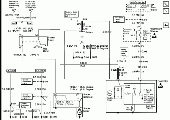
Diagrams of ignition wiring show the various wires utilized to power various components. Each component is equipped with four distinct colored connections. For accessories, red stands the starter solenoid’s color, yellow for battery, and blue for accessory. The “IGN terminal allows you to start the car, control the wipers, and any other features that operate. The diagram shows how you can connect the ACC and ST terminals to the rest of the components.
The terminal referred to as BAT is the location where the battery is. The electrical system can’t be started without the battery. The switch will not turn on if the battery isn’t there. You can refer to your wiring diagram if unsure where your car’s batteries are. The accessory terminals in your vehicle connect to the battery as well as the ignition switch. The BAT terminal is connected to the battery.
Some ignition switches come with an additional position. It allows users to connect their outputs to another location without having to turn on the ignition. Sometimes, customers may wish to utilize the auxiliary input independently of the ignition. The auxiliary output can be connected by wiring the connector with the same colors as your ignition and attaching it to the ACC terminal of the switch. Although this is a great option, there’s a thing to be aware of. The majority of ignition switches are set to operate in the ACC position when the car is in the ACC position, but they’re in the START position when the vehicle is in the IGN position.
Gallery of 97 Blazer Ignition Switch Wiring Diagram
Gallery of 97 Blazer Ignition Switch Wiring Diagram


