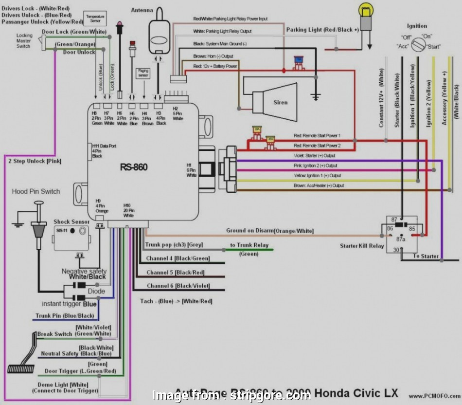
95 Civic Ignition Switch Wiring Diagram – First, we will look at the various types of terminals on the ignition switch. These are the terminals for the Ignition, Coil, or Accessory. After we’ve identified the terminals used then we can determine the various components of the 95 Civic Ignition Switch Wiring Diagram. We’ll also discuss the functions of both the Ignition Switch and the Coil. We will then discuss the functions of the Ignition switch as well as Coil.
Terminals for ignition switches
There are three separate switches on the ignition switch, and they provide the battery’s voltage to various places. The first switch powers the choke. The third switch regulates the ON/OFF switch of the ignition switch. Different manufacturers use their own color-coding systems for different conductors which is explained in a different article. OMC utilizes this system. An adapter is included on the ignition switch that allows for the addition of the Tachometer.
Even though some of the ignition switch terminals might not be original, the numbers of the terminals may not match the diagram. Before you plug into the ignition switch, make sure to check the continuity. You can do this with a simple multimeter. After you’re sure that all wires are running in good harmony then you can connect the new connector. If your car has an original ignition switch supplied by the factory (or wiring loom) The wiring loom might differ from that of your vehicle.
Before you can connect the ACC outputs to your car’s auxiliary outputs it is crucial to know the fundamentals of these connections. The ACC, IGN and START terminals are the default connection to the ignition switch. They also function as the primary connections to your radio and stereo. The ignition switch’s function is for turning the car’s engine on and off. The ignition switch terminals on older cars are labeled with the alphabets “ACC” as well as “ST” (for each magneto wires).
Terminals for Coil
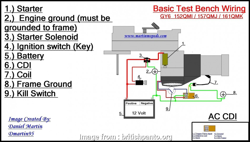
The first step in determining the kind of ignition coil is to understand the terms used. The diagram of the basic ignition wiring shows a number different connections and terminals. There are two primary and one secondary. Each coil has a specific operating voltage. To determine the type of coil you’ve got first, you need to determine the voltage at S1, the primary terminal. You should also test S1 for resistance to determine if it’s an A, B, or C coil.
The negative end of the chassis end should be connected to connect the coil’s low-tension end. This is the base of the ignition wiring. The high tension side provides positive power directly to the spark plugs. To prevent noise the coil’s metal body must be connected with the chassis. It’s not necessary to use electricity. It is also possible to see the connections of the negative and positive coil terminals on the ignition wiring diagram. In certain instances it is recommended to conduct a scan at your local auto parts shop will be able to diagnose malfunctioning ignition coils.
The black-and-white-striped wire from the harness goes to the negative terminal. The positive terminal receives the other white wire with a trace of black. The black wire connects to the contact breaker. To confirm the connections, use a paperclip or a pencil to remove them of the housing for the plug. Check that the terminals aren’t bent.
Accessory terminals
Diagrams of ignition wiring illustrate the wiring used in the power supply of the vehicle. There are usually four different colors of terminals connected to each part. For accessories, red stands for starter solenoid, blue for battery and blue for accessory. The “IGN terminal” is used to power the wipers along with other operational features. The diagram shows the connection between the ACCand ST terminals.
The battery is connected to the terminal named BAT. The electrical system will not start without the battery. In addition, the switch will not start. The wiring diagram will tell you where to find the battery of your car. The ignition switch and the battery are connected via accessory terminals. The BAT terminal is connected to the battery.
Certain ignition switches come with an accessory setting where users can alter their outputs and manage them without needing to use the ignition. Sometimes, customers may wish to utilize the auxiliary input independently of the ignition. The auxiliary output can be utilized by wiring the connector in the same colors as your ignition, and then attaching it to the ACC terminal of the switch. This is a great convenience feature however, there’s one difference. Most ignition switches are set to have an ACC position when the vehicle is in the ACC position, while they’re set to the START position when the vehicle is in the IGN position.
Gallery of 95 Civic Ignition Switch Wiring Diagram
Gallery of 95 Civic Ignition Switch Wiring Diagram


