1955 Chevy Ignition Wiring Diagram – Let’s start by looking at different types of terminals on an ignition switch. These terminals are used for the Ignition button, Coil and Accessory. Once we have established what these kinds of terminals are used for then we can identify the different parts of the 1955 Chevy Ignition Wiring Diagram. We’ll also discuss the functions and the Coil. Then, we’ll focus to the accessory terminals.
Terminals for ignition switches
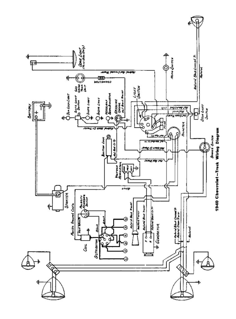
There are three different switches on the ignition switch, and they feed the battery’s voltage to several different destinations. The first switch is used to turn on the choke by pushing it, while the second is for the ON/OFF setting. Different manufacturers have different color-coding systems to identify different conductors. We will cover this in another article. OMC utilizes this system. The ignition switch comes with an option to connect the Tachometer.
Although the majority of ignition switch terminals can be duplicated, the number may not be in line with the diagram. You should first check the continuity of the wires to ensure that they are plugged into the correct ignition switch. A cheap multimeter can aid in this. Once you’re satisfied with the quality of the connection it’s time to connect the new connector. The wiring loom of an ignition system switch that is supplied by the manufacturer differs.
You must first understand how the ACC outputs and the auxiliary outputs work in order to connect them. The ACC terminals and IGN terminals function as the default connections to the ignition switch. The START and IGN connections are the primary connections for stereo and radio. The ignition switch is responsible to turn the car’s engines on and off. On older vehicles, the ignition switch terminals are identified with the alphabets “ACC”, and “ST” (for individual magnetic wires).
Terminals for coil
The terms used to define the model and type of an ignition coil is the first thing. A basic ignition wiring layout will provide you with a range of terminals and connections. Each coil has an operating voltage. The first step in determining which kind you’re using is to examine the voltage at S1 or the primary terminal. To determine if the coil is an A, C or B coil you must also test the resistance on S1’s.
The low-tension coil side must be connected to the chassis’ less. This is the wiring diagram you will see on the wiring diagram. The high-tension supply delivers the spark plugs with positive electricity directly. The aluminum body of the coil has to be linked to the chassis for suppression however it’s not electrically required. The diagram of the ignition wiring will also demonstrate the connection of the negative and positive coil’s terminals. In some instances it is possible to find an ignition coil that is malfunctioning can be diagnosed with scanning at an auto parts shop.
The black-and-white-striped wire from the harness goes to the negative terminal. The other white wire is black-colored and goes to the terminal opposite. The black wire is connected to the contact breaker. To confirm the connections, you can make use of a paperclip or pencil to pull them out of the housing for the plug. Also, make sure to ensure that the terminals have not been bent.
Accessory terminals
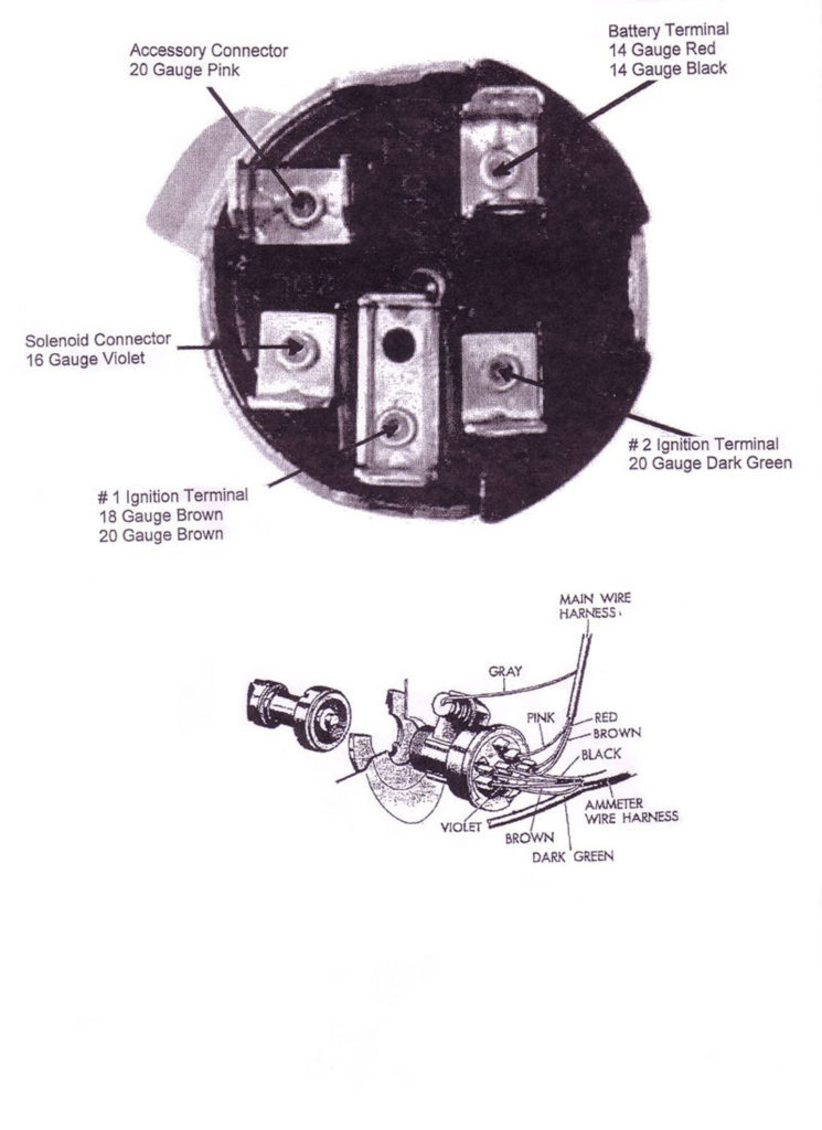
Diagrams of ignition wiring show the various wires utilized to power different components. There are generally four terminals with color codes that are connected to each component. Accessories are red and the battery yellow the starter solenoid is green. The “IGN” terminal lets you start the car, manage the wipers, and any other features that operate. The diagram shows how you can connect the ACC and ST terminals to the other components.
The terminal BAT connects the battery to the charger. The electrical system will not start without the battery. Also, the switch won’t be able to turn on without the battery. It is possible to look up your wiring diagram to determine where your car’s batteries are located. The accessory terminals of your car connect to the ignition switch as well as the battery. The BAT Terminal is connected to the Battery.
Certain ignition switches have an additional position in which users can modify their outputs as well as control them without the need to use the ignition. Sometimes, customers want to use an auxiliary output that is separate from the ignition. To use the additional output, wire the connector using the same colors as the ignition connecting it to the ACC terminal on the switch. This is a great convenience feature however there’s a difference. The majority of ignition switches are set up to have an ACC status when the vehicle is in the ACC or START positions.
Gallery of 1955 Chevy Ignition Wiring Diagram
Gallery of 1955 Chevy Ignition Wiring Diagram


