Coil Ignition Wiring Diagram – We will first look at the various types of terminals on the ignition switch. These are the terminals for the Ignition, Coil, or Accessory. When we have a clear understanding of the purpose of each kind of terminal, we are able to identify the parts of the ignition wiring. We will also talk about the functions and the Coil. After that, we’ll turn our attention to the Accessory terminals.
Ignition switch terminals
An ignition switch has three switches. They transmit the voltage of the battery to different locations. The first switch provides the choke with power when it is pushed. The second is the position of the ignition switch’s ON/OFF. Every manufacturer has its individual color-coding system that we’ll go over in a separate article. OMC uses the same method. The connector permits the attachment of a speedometer the ignition switch.
Even though many ignition switch terminals do not have the original design, the numbering may not match that of the diagram. Check the continuity of the wires to determine if they’re connected to the ignition switch correctly. A cheap multimeter can assist you in this. Once you’re satisfied with the connection then you can connect the new connector. If your car has an ignition switch installed the wiring diagram may differ.
It is important to know the differences between the ACC and the auxiliary outputs. The ACC and IGN connectors are the standard connections for your ignition switch. While the START, IGN, and ACC terminals are the main connections for radios or stereo, the START/IGN terminals are the primary ones. The ignition switch is the one that controls the engine of your car. The terminals of the ignition switch on older cars are labeled with the initials “ACC” and “ST” (for each magneto wires).
Terminals for Coil
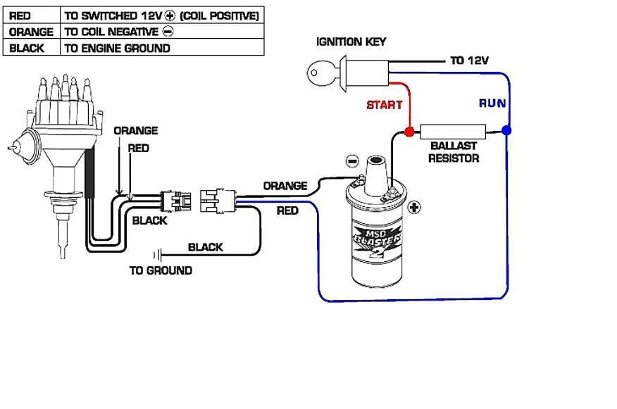
The terminology used to determine the model and type of the ignition coil is the most important thing. An understanding of the basic wiring diagram for ignition will provide you with a range of terminals and connections. The coils come with a distinct operating voltage. The first method of determining what type you’re using is to test the voltage at S1, the main terminal. S1 must be tested for resistance in order to determine if the coil is Type A, B, and/or C.
The coil’s low-tension side must be connected with the chassis’ positive. This is what you see in the wiring diagram. The high-tension component provides the spark plugs with positive. To prevent noise the body of the coil must be connected to chassis. However, it is not required to connect electrically. A wiring diagram can show the connection between the positive and negative coils. In certain instances, a scan at the local auto parts store can help you identify malfunctioning ignition coils.
The black-and-white-striped wire from the harness goes to the negative terminal. The terminal for the negative is served by the black trace attached to the white wire. The black wire is connected to the contact breaker. If you’re unsure of the connections between the two, try using a paper clip to remove them from the plug housing. It is also important to make sure that the connections aren’t bent.
Accessory terminals
Diagrams of the ignition wiring show the wiring used to supply power to different parts of the vehicle. There are usually four different color-coded terminals to each component. For accessories, red stands for starter solenoid, yellow is for battery, and blue is for accessories. The “IGN” terminal is used to start the car and operate the wipers as well as other operational functions. This diagram shows how to connect ACC and ST terminals with the other components.
The terminal BAT is the connection to the battery. The electrical system won’t start if the battery isn’t connected. Furthermore, the switch won’t start. You may refer to the wiring diagram if not sure where the batteries of your car are located. The ignition switch is connected to the car’s battery. The BAT terminal connects to the battery.
Certain ignition switches provide the option of an “accessory position” that allows users to adjust their outputs independently of the ignition. Sometimes, users want to use an auxiliary output that is independent of the ignition. For the auxiliary output to be used, plug in the connector to the same shade as the ignition. Connect it to the ACC end of the switch. While this is an excellent feature, there’s something you need to know. Some ignition switches are programmed to have an ACC location when the car has moved into the ACC position. They will also be in the START mode once the vehicle is entered the IGN position.
Gallery of Coil Ignition Wiring Diagram
Gallery of Coil Ignition Wiring Diagram


