Motorcycle Cdi Ignition Wiring Diagram – We will first look at the various kinds and functions of terminals in the ignition switches. These include the terminals for the Ignition switch, Coil, and Accessory. Once we know the purpose of each terminal, we are able to determine the components of the ignition wiring. We’ll also be discussing the functions of the Ignition switch and Coil. Then, we’ll talk about the roles of the Ignition switch as well as Coil.
Terminals of ignition switch
An ignition switch is comprised of three switches. They transmit the voltage of the battery to many different places. The ON/OFF state of the switch that controls the ignition is managed by the second switch, which delivers the choke with power when it is pushed. Different manufacturers use different color codes for various conductors. This is explained in another article. OMC utilizes this system. An adapter is included on the ignition switch to allow the installation of a Tachometer.
Although the majority of ignition switch terminals are duplicated, the numbers may not be consistent with the diagram. You should first check the electrical continuity to ensure that they are connected to the ignition switch in the correct way. A simple multimeter will assist you in this. When you’re satisfied with the integrity of the wires, then you’ll be able to connect the new connector. If your vehicle has an original ignition switch supplied by the factory (or wiring loom) the wiring loom may differ from the one in the car.
First, understand the differences between the ACC and auxiliary outputs. The ACC, IGN and START terminals are the primary connections to the ignition switch. They are also the primary connections to your radio and stereo. The ignition switch is the one that controls the engine of your car. Older vehicles have ignition switch terminals labeled “ACC” or “ST” (for individual magnetowires).
Terminals for coil
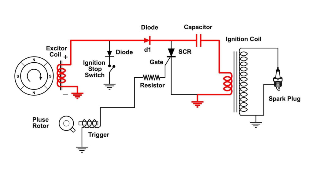
Understanding the terminology that is used is the initial step in determining what type of ignition coil. There are a variety of connections and terminals within a basic ignition wiring schematic that include two primary and two secondary. The coils come with a distinct operating voltage. The first method of determining what type you’ve got is to check the voltage at S1, the main terminal. S1 must be tested for resistance in order to determine if the coil belongs to type A, B or C.
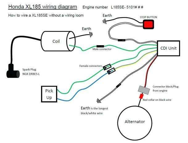
The coil’s low-tension side must be connected to the chassis positively. This is also the ground on an ignition wiring diagram. The high-tension part provides the spark plugs with positive. The aluminum body of the coil has to be connected to the chassis to prevent it from being smothered but isn’t required. The ignition wiring diagram will also reveal the connection of the negative and positive coil terminals. Sometimes, an inspection at an auto parts store could detect a defective ignition wire.
The black-and-white-striped wire from the harness goes to the negative terminal. The white wire also is black with a trace, and it goes to the positive terminal. The contact breaker is connected to the black wire. To check the connections, employ a paperclip, or a pencil to lift them out of the plug housing. Be sure that you don’t bend the connectors.
Accessory Terminals
The ignition wiring diagrams illustrate the various wires that are used to power various components of the car. There are usually four colors-coded terminus of each part. Red is for accessories, yellow is for the battery, while green is the starter solenoid. The “IGN terminal lets you start the car, control the wipers, or any other operation features. The diagram illustrates how to connect ACC or ST terminals, and other.
The terminal BAT is the connection to the battery. The electrical system is not able to start without the battery. A dead battery can make the switch stop turning on. A wiring diagram can tell you where to find the battery of your car. The ignition switch as well as the battery are connected by the accessory terminals. The BAT terminal is connected with the battery.
Some ignition switches have the “accessory” setting that allows users to control their outputs , without having to use the ignition. Some customers may prefer to use the auxiliary output in addition to the ignition. You can use the auxiliary output by connecting it to the ACC terminal on the switch with the same colors. While this is an excellent option, there’s a thing you should know. The majority of ignition switches are set up to have an ACC status when the car’s at either the ACC or START positions.
Gallery of Motorcycle Cdi Ignition Wiring Diagram
Gallery of Motorcycle Cdi Ignition Wiring Diagram


