12 Volt Ignition Switch Wiring Diagram – First, let’s examine the various terminals that are used in the ignition switch. These terminals serve for the Ignition button, Coil and Accessory. Once we have established what these kinds of terminals are used for then we can identify the different parts of the 12 Volt Ignition Switch Wiring Diagram. We’ll also be discussing the functions of the Ignition switch, and Coil. Then, we will concentrate on the accessories terminals.
Terminals of ignition switch
An ignition switch is composed of three different switches. These are responsible for feeding the battery’s power to various destinations. The first switch provides power to the choke when pushed, and the second is the switch that controls the ignition’s ON/OFF positions. Each manufacturer has their individual color-coding system that we’ll go over in a separate article. OMC follows this scheme. A connector can be added to the ignition switch to add a digital tachometer.
While most ignition switch terminals can be duplicated, the number may not match the diagram. First, check the continuity of each wire to ensure that they are properly plugged into the ignition switches. This can be checked using a cheap multimeter. After you’re happy with the integrity of your wires, you will be able to connect the new connector. The wiring loom used in the ignition system switch supplied by the manufacturer differs.
Before you can connect the ACC outputs to the auxiliary outputs of your car it is crucial to know the fundamentals of these connections. The ACC and IGN connectors are the standard connections for the ignition switch. Although the START, IGN, and ACC terminals are the primary connections for the radio or stereo, the START/IGN terminals are the main ones. The ignition switch acts as the engine’s off/on button. The terminals of the ignition switch on older cars are identified with the alphabets “ACC” as well as “ST” (for each magneto wires).
Coil terminals
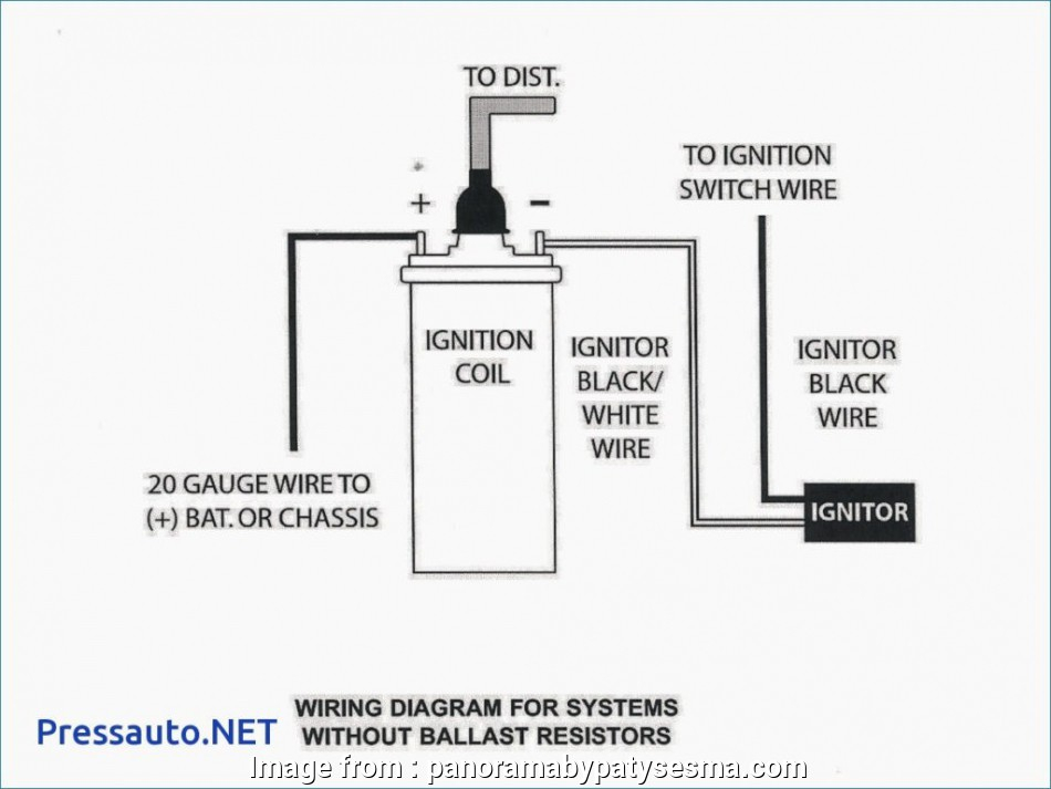
The language used to decide the model and type of an ignition coil is the first thing. The basic ignition wiring diagram depicts various connections and terminals. There are two primary and secondary connections. The operating voltage of every coil is different. This is why it is essential to first check the voltage at the S1 (primary terminal). To determine if the coil is a Type A, C or B coil you must also check the resistance of S1.
The coil’s low-tension side should be connected to the chassis’s plus. This is what’s called the ground on the diagram of ignition wiring. The high-tension part supplies positive direct to the sparkplugs. To prevent noise the body of the coil must be connected to the chassis. But, it’s not necessary to connect the coil electrically. The ignition wiring diagram will also reveal the connections between the negative and positive coil’s terminals. In certain instances, you’ll find that an ignition coil that is malfunctioning is easily identified with scans at an auto parts shop.
The black-and-white-striped wire from the harness goes to the negative terminal. The other white wire is black with a trace on it, and it connects to the positive terminal. The black wire connects to the contact breaker. It is possible to check the connections with a pencil to pull the wires out of the housing. Be sure to check that the terminals aren’t bent.
Accessory terminals
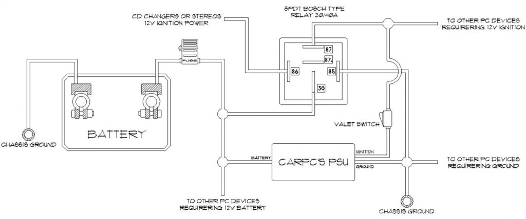
The wiring diagrams for the ignition show the various wires that power the various components of the car. There are generally four terminals with color codes that are connected to each component. The accessories are red and the battery yellow and the starter solenoid is green. The “IGN” terminal can be used to start the car and operate the wipers as well as other operational features. The diagram illustrates the connection to the ACCas well as ST terminals.
The terminal referred to as BAT is the place where the battery is. Without the battery the electrical system will not get started. The switch won’t turn on if there is no battery present. If you’re not sure of where your car’s battery is located, you can look at the wiring diagram of your car to determine the best way to find it. The accessory terminals on your vehicle are connected to the battery as well as the ignition switch. The BAT Terminal is connected to the Battery.
Certain ignition switches come with the “accessory” position that allows users to control their outputs without needing to turn on the ignition. Sometimes, customers want to utilize an additional output that is independent of the ignition. To use the auxiliary output, wire the connector with the same colors as ignition, connecting it to the ACC terminal on the switch. This is a great convenience feature, but there is one distinction. Most ignition switches come with the ACC position when your vehicle is in the ACC mode and a START mode when it is in IGN.
Gallery of 12 Volt Ignition Switch Wiring Diagram
Gallery of 12 Volt Ignition Switch Wiring Diagram


