Ignition Switch Wiring Diagram For Lawn Mower – We will first take a look at the various kinds of terminals on the ignition switch. These terminals are used for the Ignition button, Coil and Accessory. Once we’ve determined the function of the terminals we can identify the various parts of the ignition wiring. Then, we will discuss the functions and the Coil. After that, we’ll turn our attention to the Accessory terminals.
Terminals for ignition switches
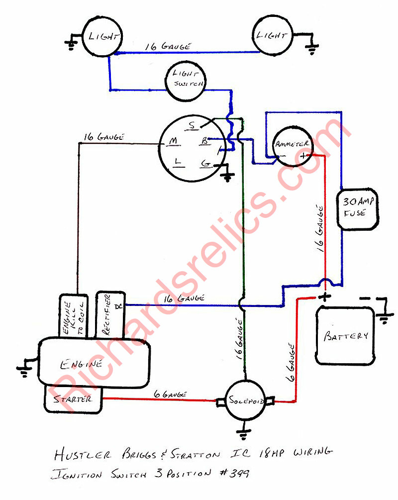
The ignition switch has three switches. They supply the voltage of the battery to many different places. The ON/OFF position of the ignition switch is controlled by the third switch, which supplies power to the choke when it is pushed. Different manufacturers have different color-coding systems for different conductors. This will be covered in a different article. OMC uses this system. An adapter is included on the ignition switch, allowing for the addition of a Tachometer.
While the majority of the ignition switch terminals are not authentic, the numbering of each one may not be in line with the diagram. Check the integrity of the wires first to make sure they’re properly connected to the ignition switch. You can do this with an inexpensive multimeter. When you’re satisfied that the wires are running in good harmony and you are able to connect the new connector. If you’re using a factory-supplied ignition switch the wiring loom will be distinct from the one that is used in your vehicle.
It is essential to know the way that ACC outputs and the auxiliary outputs function in order to join them. The ACC/IGN connections function as the default connections on the ignition switch. The START/IGN terminals are connected to the stereo or radio. The ignition switch is the engine’s switch to turn off or on. The terminals on older cars ignition switches are identified by “ACC” as well as ST (for individual magneto wires).
Terminals for coil
Understanding the terminology utilized is the initial step in determining the kind of ignition coil to choose. The fundamental diagram of ignition wiring depicts various connections and terminals. There are two primary and one secondary. The coils are equipped with a particular operating voltage, and the first step in determining which type you’ve got is to check the voltage of S1 the primary terminal. Also, you should test S1 for resistance in order to determine if it’s an A B, C, or coil.
The coil’s low-tension side must be connected with the chassis positively. This is what’s called the ground in the ignition wiring diagram. The high-tension part is a positive connection to the sparkplugs. To reduce the noise, the coil’s metal body is required to be connected to the chassis. However, it is not required to connect electrically. The ignition wiring diagram will also outline how to connect the positive coil’s terminals. There could be an issue with your ignition coil that is easily identified by scanning it at an auto parts store.
The black-and-white-striped wire from the harness goes to the negative terminal. The terminal that is negative is served by the trace in black that’s connected to the white wire. The black wire is connected to the contact breaker. You can take the black wire from the plug housing by using a paperclip in case you are uncertain about the connections. Be sure that the terminals aren’t bent.
Accessory terminals
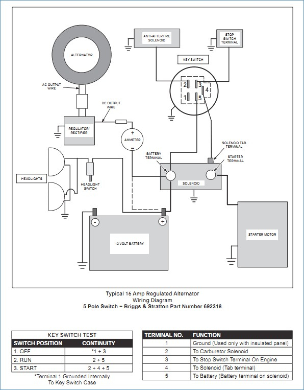
Diagrams of ignition wiring depict the wires that are used in the power supply of the vehicle. There are typically four different color-coded terminus for each component. Red is used for accessories while yellow is the battery, and green is for the solenoid for starters. The “IGN” terminal can be used to start the car, operate the wipers, and other features. The diagram illustrates how to connect ACC or ST terminals as well as the rest.
The terminal BAT is the connection for the battery. Without the battery the electrical system can not start. The switch won’t turn off if the battery isn’t there. It is possible to refer to your wiring diagram if unsure where your car’s batteries are located. The ignition switch and the battery are connected via accessory terminals. The BAT connector is connected to the battery.
Some ignition switches come with a separate “accessory” location, which allows users can manage their outputs with no ignition. Customers sometimes want an auxiliary output that can be used separately from the ignition. You can use the auxiliary input by connecting the connector to the ACC terminal. This feature of convenience is fantastic, but there is one distinction. Many ignition switches have the ACC position when the car is in ACC mode, and a START position when you are in IGN.
Gallery of Ignition Switch Wiring Diagram For Lawn Mower
Gallery of Ignition Switch Wiring Diagram For Lawn Mower


