Dyna S Dual Fire Ignition Wiring Diagram – First, let’s take a look at the different types of terminals used on the ignition switch. These terminals serve for the Ignition button, Coil and Accessory. Once we’ve determined the function of the terminals we will be able to determine the various components of the ignition wiring. We will also discuss the roles of the Ignition switch and Coil. Following that, we’ll shift our attention to Accessory terminals.
Terminals of ignition switch
An ignition switch contains three switches that supply the battery’s current to different destinations. The first switch provides power to the choke whenever pushed, and the second is the ignition switch’s ON/OFF position. Different manufacturers employ various color codes for the different conductors. This is described in a separate article. OMC utilizes the same system. Connectors can be connected to the ignition switch to add a digital Tachometer.
While the majority of ignition switch terminals do not appear in their original configuration The numbering might not match the diagram. Before plugging in the ignition switch, ensure that you check the continuity. You can check this using a simple multimeter. When you’re satisfied with the continuity of the wires, then you’ll be able install the new connector. If your vehicle is equipped with an ignition switch installed the wiring diagram may differ.
In order to connect the ACC outputs to the auxiliary outputs on your car, you’ll need to understand the way these two connections function. The ACC, IGN and START terminals are the primary connection to the ignition switch. They also function as the primary connections to your radio and stereo. The ignition switch is responsible for turning the engine of your car to and off. Older cars are identified with the alphabets “ACC”, “ST”, (for individual magneto cables) at their ignition switch terminals.
Terminals for coil
Understanding the terms utilized is the first step in determining the kind of ignition coil you need. There are a variety of connections and terminals on a basic ignition wiring schematic which includes two primary and two secondary. Each coil comes with its own operating voltage. To determine which type of coil you own the first step is to determine the voltage at S1, the primary terminal. You should also examine S1 for resistance in order to identify if it’s a Type A, B, or C coil.
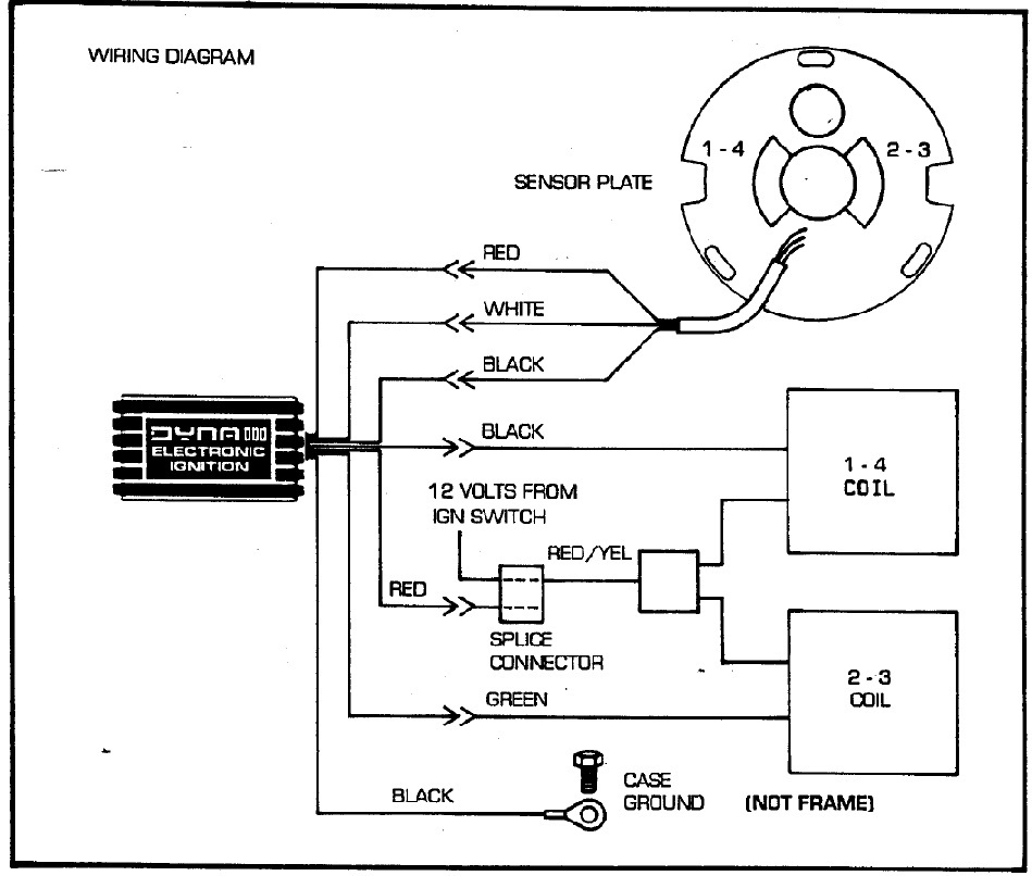
The coil’s low-tension end must be connected to the chassis’ positive. This is the ground of the wiring for ignition. The high-tension supply supplies positive directly to spark plugs. To prevent noise the coil’s body metal is required to be connected to the chassis. It’s not necessary for electrical use. A wiring diagram can also depict the connection between positive and negative coils. In certain cases scanning your local auto parts store will be able to diagnose malfunctioning ignition coils.
The black-and-white-striped wire from the harness goes to the negative terminal. The positive terminal also receives the second white wire, which is black in its trace. The black wire connects to the contact breaker. To test the connections between the two wires, use a paperclip to remove them off the housing. Make sure that the connectors do not bend.
Accessory terminals

Diagrams of ignition wiring show the wires that provide power to various components of the vehicle. Each component is equipped with four distinct colored connections. Red refers to accessories, yellow is the battery and green is the starter solenoid. The “IGN” terminal is used to start the vehicle and control the wipers and other operating functions. The diagram shows the connection of the ACC- and ST terminals.
The terminal referred to as BAT is where the battery is connected. The electrical system cannot start without the battery. Also, the switch won’t be able to turn on without the battery. You can refer to your wiring diagram if you are uncertain about where the car’s batteries are. The accessory terminals of your car connect to the ignition switch and the battery. The BAT terminal is connected to the battery.
Certain ignition switches come with an “accessory” setting that permits users to regulate their outputs without needing to utilize the ignition. Sometimes, users want to use an auxiliary output that is independent of the ignition. To use the auxiliary output, wire the connector with the same colors as the ignition, and connect it to the ACC terminal on the switch. This feature is convenient however it does have one major distinction. The majority of ignition switches are designed to have an ACC status when the car is at either the ACC or START position.
Gallery of Dyna S Dual Fire Ignition Wiring Diagram
Gallery of Dyna S Dual Fire Ignition Wiring Diagram


